-
Products
-
SonicPlatform
SonicPlatform is the cybersecurity platform purpose-built for MSPs, making managing complex security environments among multiple tenants easy and streamlined.
Discover More
-
-
Solutions
-
Federal
Protect Federal Agencies and Networks with scalable, purpose-built cybersecurity solutions
Learn MoreFederalProtect Federal Agencies and Networks with scalable, purpose-built cybersecurity solutions
Learn More - Industries
- Use Cases
-
-
Partners
-
Partner Portal
Access to deal registration, MDF, sales and marketing tools, training and more
Learn MorePartner PortalAccess to deal registration, MDF, sales and marketing tools, training and more
Learn More - SonicWall Partners
- Partner Resources
-
-
Support
-
Support Portal
Find answers to your questions by searching across our knowledge base, community, technical documentation and video tutorials
Learn MoreSupport PortalFind answers to your questions by searching across our knowledge base, community, technical documentation and video tutorials
Learn More - Support
- Resources
- Capture Labs
-
- Company
- Contact Us
Router on a Stick configuration using SonicWall Switch


Description
This article explains the steps for Router on a Stick configuration using SonicWall switch while using common uplink or dedicated uplink.
Router-on-a-stick is a term frequently used to describe a setup up that consists of a router and switch connected using one Ethernet link configured as an 802.1q trunk link. In this setup, the switch is configured with multiple VLANs and the router performs all routing between the different networks/VLANs.
Resolution
We can have Router on a Stick configuration using common uplink or dedicated uplink. In both scenarios, the VLAN sub-interfaces are to be added on the firewall first. Once done, we can assign the roles correctly to the switch ports.
For creating VLAN sub-interfaces on the firewall, please refer How Can I Configure Sub-Interfaces?
When two devices communicate that belong to the same VLAN, the traffic is directly sent through the switch. When devices from two separate VLANs try to communicate, the traffic needs to come to the SonicWall firewall which will perform inter-VLAN routing.
 EXAMPLE 1: Router on a Stick configuration with common uplink
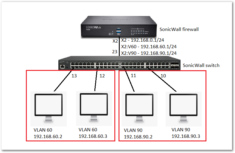
- Let us consider we have SonicWall switch connected to the X2 interface of the SonicWall firewall. X2 interface is on zone LAN with IP: 192.68.0.1/24 and also two sub-interfaces X2: V60 with 192.168.60.1/24 and X2: V90 with 192.168.90.1/24. We have four endpoint devices connected to switches on different VLANs with their respective IP schemes. Port 23 of the switch is connected as a common uplink and management port to interface X2.
Switch configuration:
- Port 23: Trunk port allowing both VLANs 60 and 90.
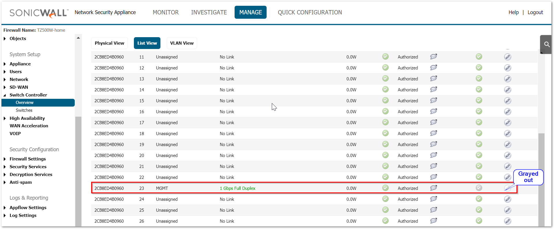
- Since port 23 is used for management it is by default a trunk port as it carries both management and data traffic. We will not be able to make any changes to this port. Navigate to MANAGE | Switch Controller | Overview tab and you can see the same under List View.
To create the access ports:
- Navigate to MANAGE | Switch Controller | Overview tab. You can configure the ports from either physical view, List view or VLAN view.
- Port 10 and 11: Access ports with VLAN 90.
• Click on port 10 and make sure that the port enable is toggled to ON state.
• Port shield it to interface X2 as that interface has VLAN 90 configured
• Also from the list of VLANs under VLANs available, move 90 to VLANs selected using the right arrow.
• Click OK.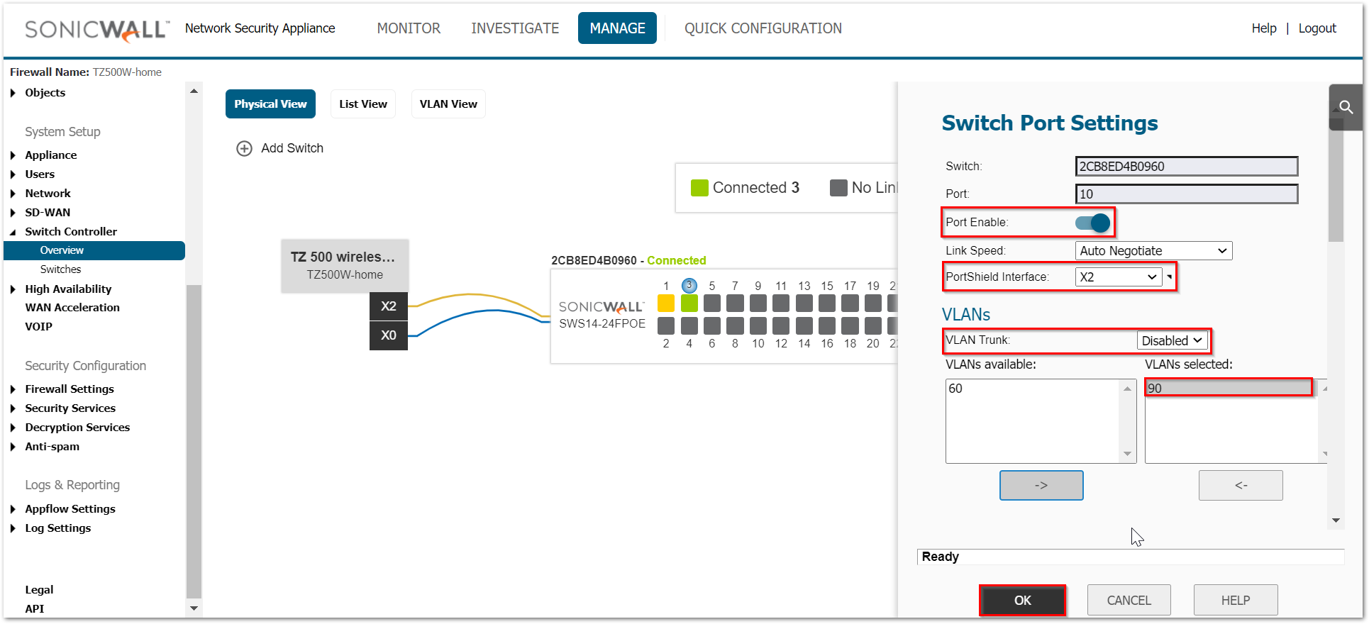
• Repeat the same steps for port 11. - Port 12 and 13: Access ports with VLAN 60.
• Click on port 12 and make sure that the port enable is toggled to ON state.
• Port shield it to interface X2 as that interface has VLAN 60 configured.
• Also from the list of VLANs under VLANs available, move 60 to VLANs selected using the right arrow.
• Click OK.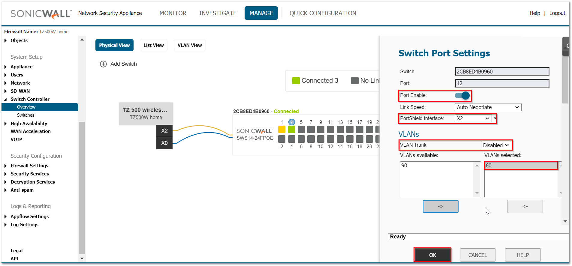
• Repeat the same steps for port 13.
 EXAMPLE 2: Router on a Stick configuration with dedicated uplink.
- Let us consider we have SonicWall switch connected to the X2 interface of the SonicWall firewall. X2 interface is on zone LAN with IP: 192.68.0.1/24. We have interface X0 on IP: 192.168.181.1/24 and two sub-interfaces X0: V190 with 192.168.190.1/24 and X2: V195 with 192.168.195.1/24 We have four endpoint devices connected to switches on different VLANs with their respective IP schemes. Port 23 of the switch is connected as a common uplink and management port to interface X2. Port 3 is used as the dedicated uplink for X0.
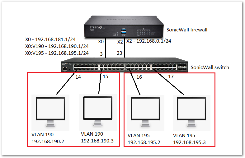
Switch configuration:
To create trunk port:
- Navigate to MANAGE | Switch Controller | Overview tab. You can configure the ports from either physical view, List view or VLAN view.
- Port 3: Trunk port allowing both VLANs 190 and 195.
• Click on port 3 and make sure that the port enable is toggled to ON state.
• Port shield it to interface X0 as that interface has VLANs 190 and 195 configured
• Dedicated Uplink for X0 toggle switch should be enabled
• Click OK.
Since this is a dedicated uplink for X0 and already has the VLAN sub-interfaces configured under X0, it automatically becomes a trunk port.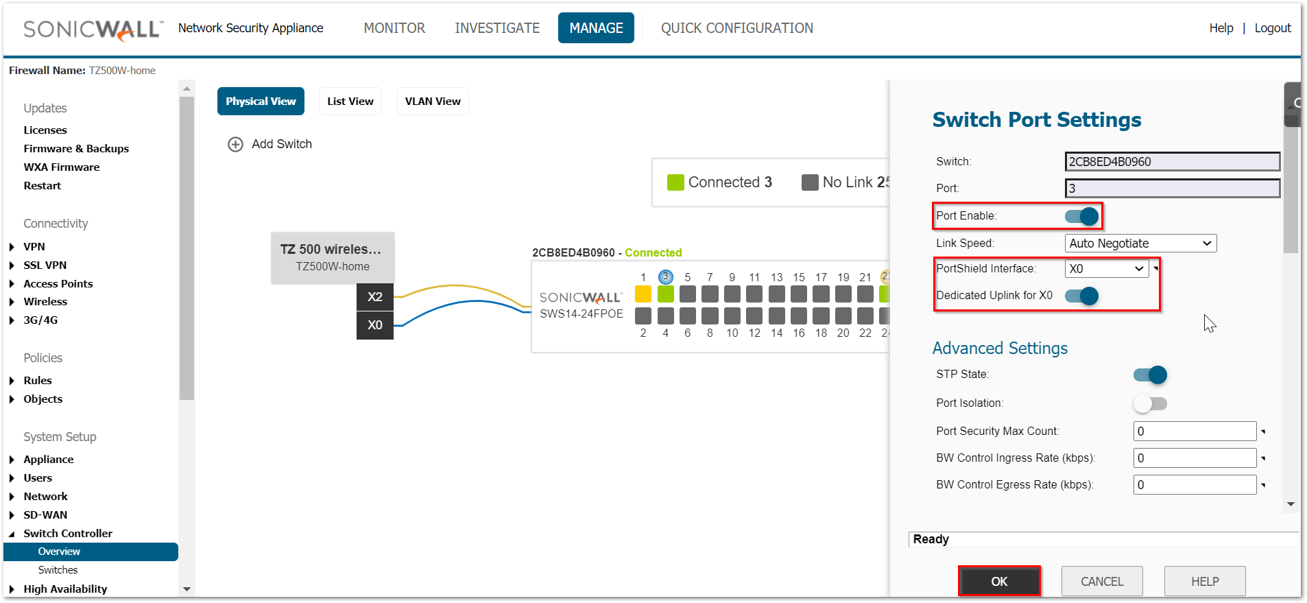
To create the access ports:
- Navigate to MANAGE | Switch Controller | Overview tab. You can configure the ports from either physical view, List view or VLAN view.
- Port 14 and 15: Access ports with VLAN 190.
• Click on port 14 and make sure that the port enable is toggled to ON state.
• Port shield it to interface X0 as that interface has VLAN 190 configured.
• Also from the list of VLANs under VLANs available, move 190 to VLANs selected using the right arrow.
• Click OK.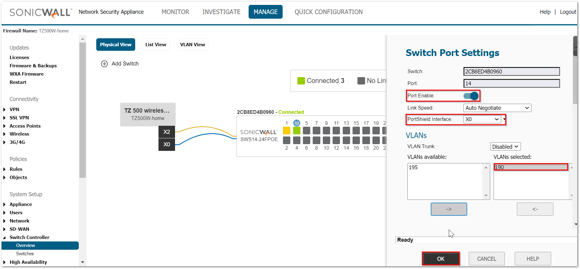
• Repeat the same steps for port 15. - Port 16 and 17: Access ports with VLAN 195.
• Click on port 16 and make sure that the port enable is toggled to ON state.
• Port shield it to interface X0 as that interface has VLAN 195 configured
• Also from the list of VLANs under VLANs available, move 195 to VLANs selected using the right arrow.
• Click OK.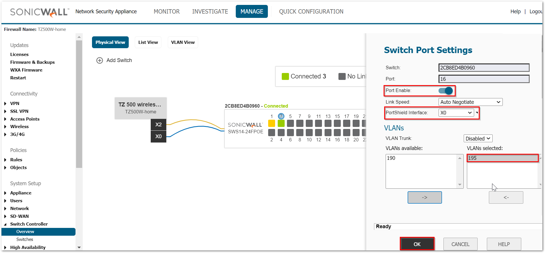
• Repeat the same steps for port 17.
Related Articles
- Supported SonicWall and 3rd party SFP and SFP+ Modules that can be used with SonicWall Switches
- How to enable Port Mirror on Sonicwall Switch.
- Create a new VLAN on Sonicwall Switch managed by WCM.


 YES
YES NO
NO