-
Products
-
SonicPlatform
SonicPlatform is the cybersecurity platform purpose-built for MSPs, making managing complex security environments among multiple tenants easy and streamlined.
Discover More
-
-
Solutions
-
Federal
Protect Federal Agencies and Networks with scalable, purpose-built cybersecurity solutions
Learn MoreFederalProtect Federal Agencies and Networks with scalable, purpose-built cybersecurity solutions
Learn More - Industries
- Use Cases
-
-
Partners
-
Partner Portal
Access to deal registration, MDF, sales and marketing tools, training and more
Learn MorePartner PortalAccess to deal registration, MDF, sales and marketing tools, training and more
Learn More - SonicWall Partners
- Partner Resources
-
-
Support
-
Support Portal
Find answers to your questions by searching across our knowledge base, community, technical documentation and video tutorials
Learn MoreSupport PortalFind answers to your questions by searching across our knowledge base, community, technical documentation and video tutorials
Learn More - Support
- Resources
- Capture Labs
-
- Company
- Contact Us
FIPS Mode: Radius protected with IPSEC VPN


Description
The following article shows how to configure an IPSEC VPN to protect Radius authentication on a firewall configured to operate in FIPS-mode.
In this Scenario the VPN is between the firewall and internal Radius server on Windows Server 2016 but same configuration works also on subsequent versions.
Cause
One of the key requirements to enable FIPS mode on a SonicWall Firewall is to protect Radius authentication with IPSEC VPN.
To understand better how FIPS mode work please refer to the KB Article How do I enable FIPS Mode?
Resolution
NETWORK PREREQUISITES
X0 must be connected even if the Radius is connected to another Interface: since by design the traffic to the Radius Server is initiated from X0 IP, if X0 is not used or there is no cable connected the firewall will establish the VPN but traffic to the Radius server will not be sent through the tunnel. Be sure to have a cable connected to X0 interfaces. In case of HA, both X0 must be connected because in case of fail over the unit that becomes active (stand-by to active) must have the same links as the unit that was working as primary.
SCENARIO

In this particular scenario the Radius Server is connected to the X0 Subnet - LAN zone.
Please also check the following video which guides through the configuration steps of a Site-to-Site VPN between SonicWall and Windows Server (the video uses Windows 2012 R2 as example but it's applicable to Server 2016). VIDEO: How to configure a Site-to-Site VPN between SonicWall and Windows Server
WINDOWS SERVER CONFIGURATION
Enable the Routing and Remote Access Services role using the Server Manager.
- Click the “Add roles and features” option. Alternatively, you can find it under the “Manage” menu on the top right.

- Click “Next” on the “Before you begin” screen.
- Select “Role-based or feature-based installation” and click “Next”.
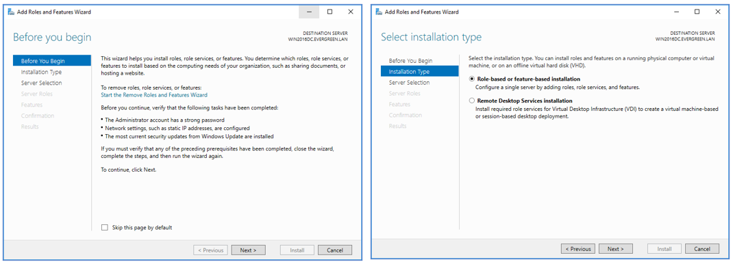
- Click “Select a server from the server pool”, and select the local server. Click “Next”.
- Scroll down to “Remote Access”, and select it. Click “Next”. Click “Next” again to skip the “Features” section.
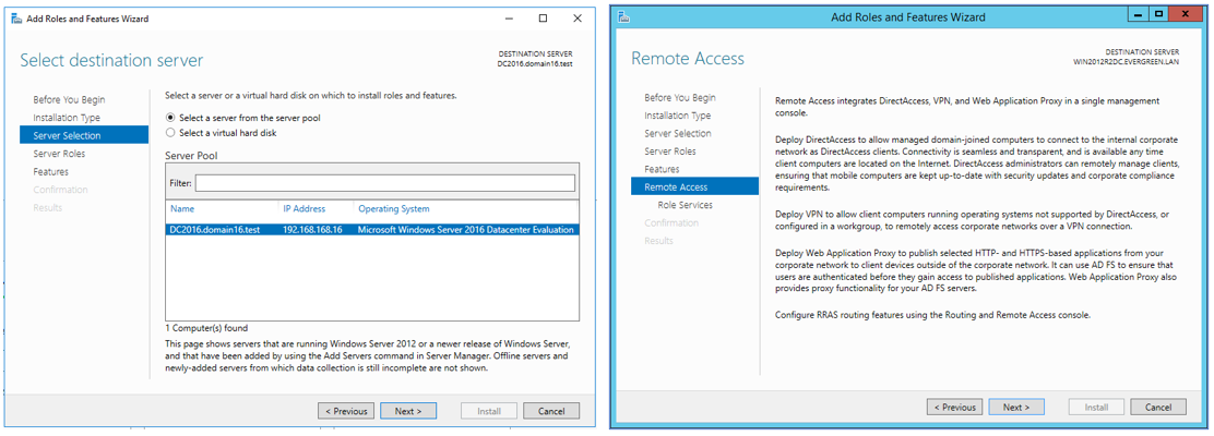
- On the “Remote Access” section that provides information about DirectAccess, VPN, and Web Application Proxy, click “Next”.
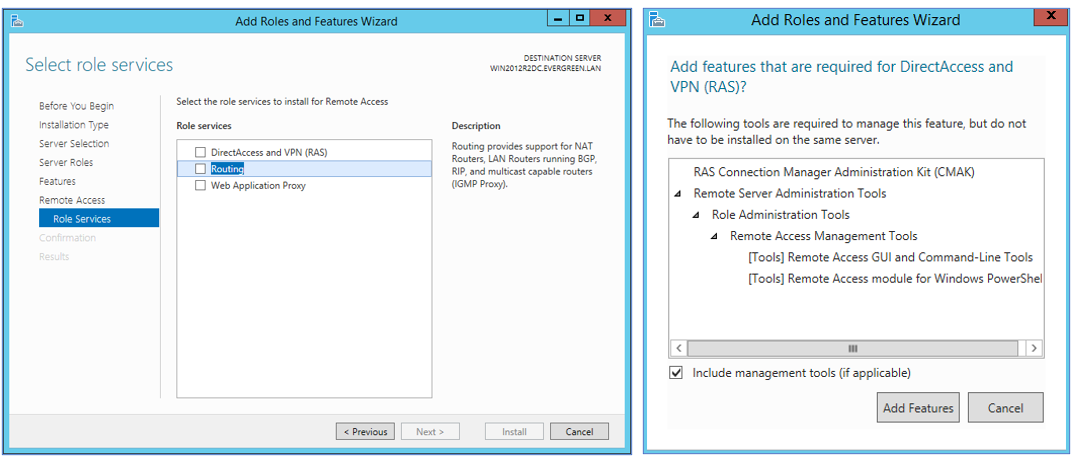
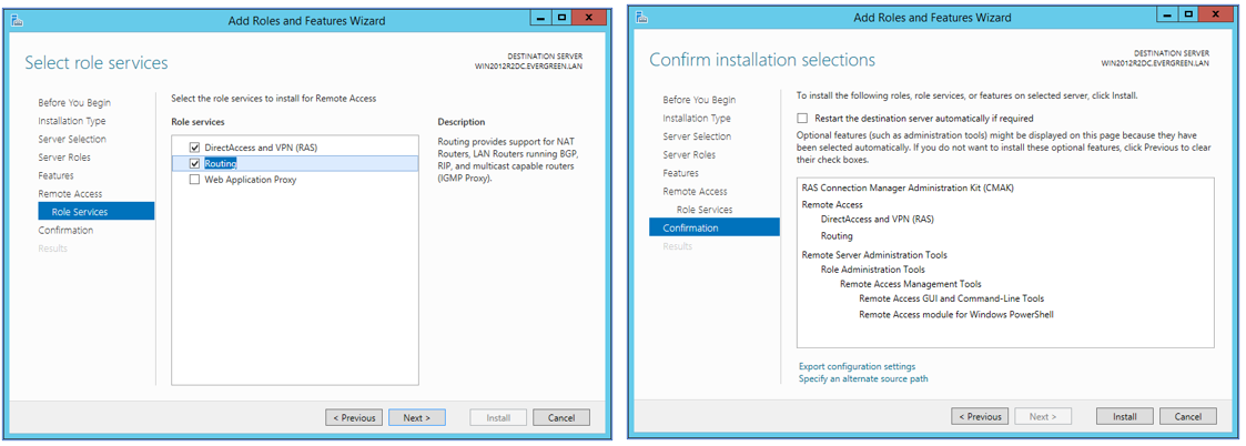
- On the “Role Services” section, select/check both “DirectAccess and VPN (RAS)” and “Routing”. If/when you are prompted to install additional feature requirements, click “Add Features”. Click “Next”.
- Finally, on the “Confirm installation selections” section, click “Install”. Optionally, enable/check the “Restart the destination server automatically if required” to do so during the installation. Otherwise, you can plan to restart manually at a convenient time if required.
Configure Routing and Remote Access Services.
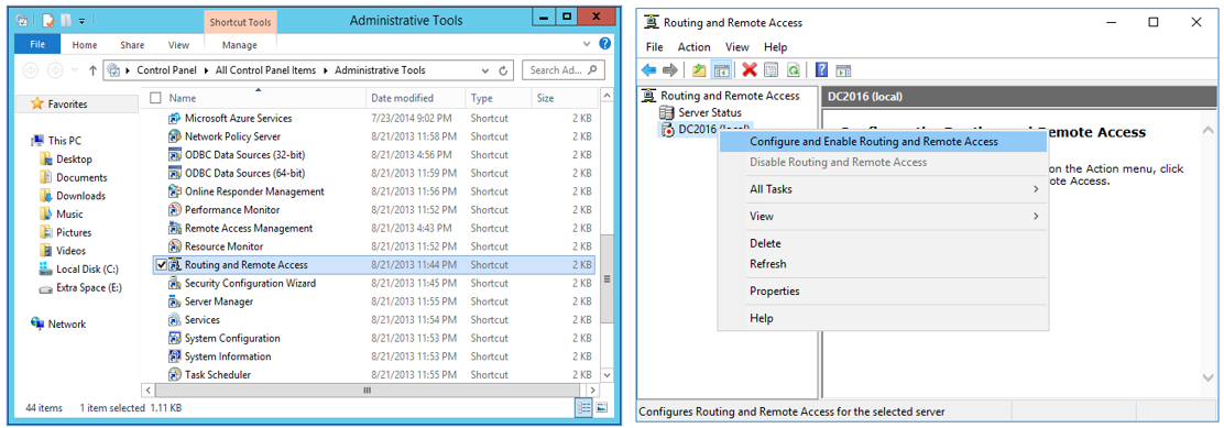
- Open “Routing and Remote Access” from the Administrative Tools folder in the Control Panel.
- Right-click on the “ (local)” entry. Click “Configure and Enable Routing and Remote Access”.
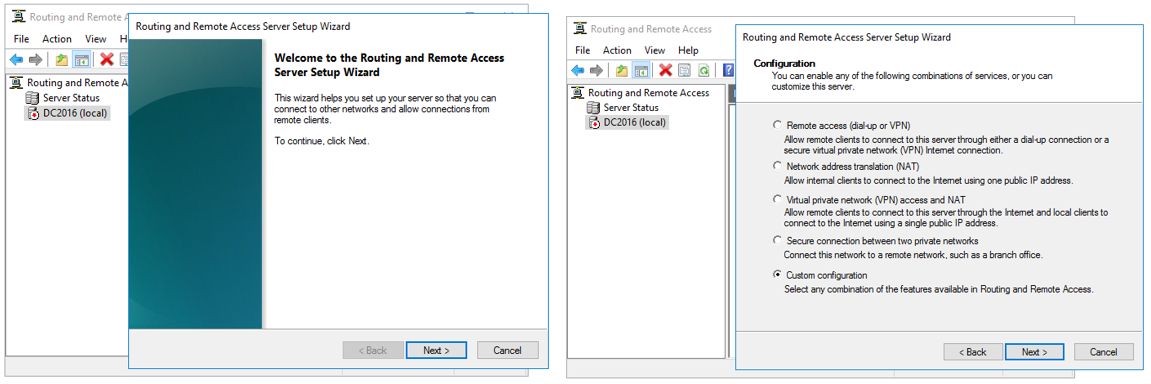
- On the Welcome screen, click “Next”.
- On the Configuration screen, click “Custom configuration” and click “Next”.
- On the Custom Configuration screen, select “LAN routing” and click “Next”. Click “Finish”.
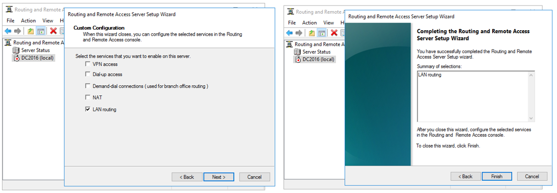
- Review the prompt from Routing and Remote Access, then click “OK”. Click “Start service” on the next prompt informing you that the Routing and Remote Access service is ready to use. Wait for the service to start.

- Close Routing and Remote Access.
1. Configuring the Windows Firewall with Advanced Security.
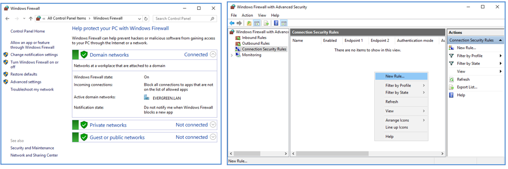
- Open the Windows Firewall under Control Panel.
- Click “Advanced settings” on the left panel. The “Windows Firewall with Advanced Security” will open.
- Click on “Connection Security Rules” on the left panel. Create a new rule in the “Connection Security Rules” section.
- On the Rule Type screen, select “Tunnel”. Click “Next”.
- On the Tunnel Type screen, select “Custom configuration” and “No. Send all network traffic that matches this connection security rule through the tunnel”. Click “Next”.
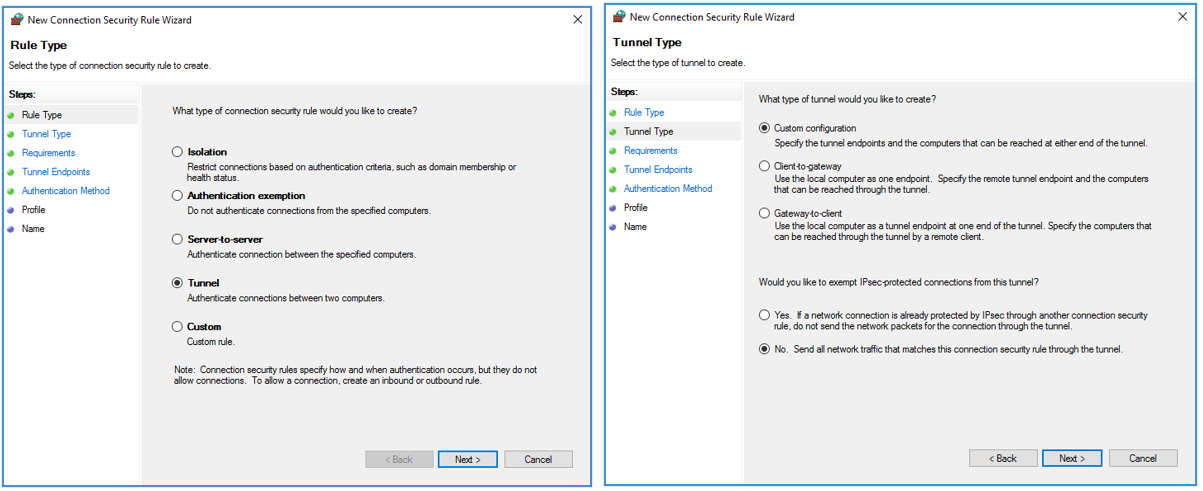
- On the Requirements screen, select “Require authentication for inbound and outbound connections”. Click “Next”.
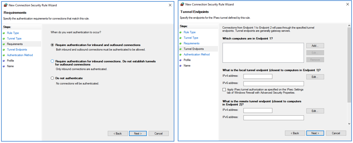
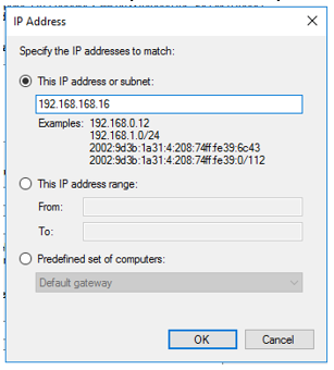
- In “Which computers are in Endpoint 1?” click on “Add…” and enter the server IP address: 192.168.168.16.
- In “What is the local tunnel endpoint (closest to computers in Endpoint 1)?” click on “Edit…” and enter the server IP address: 192.168.168.16.
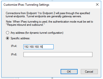
- In “What is the local tunnel endpoint (closest to computers in Endpoint 2)?” click on “Edit…” and enter the firewall IP address: 192.168.168.168. Click “OK”.
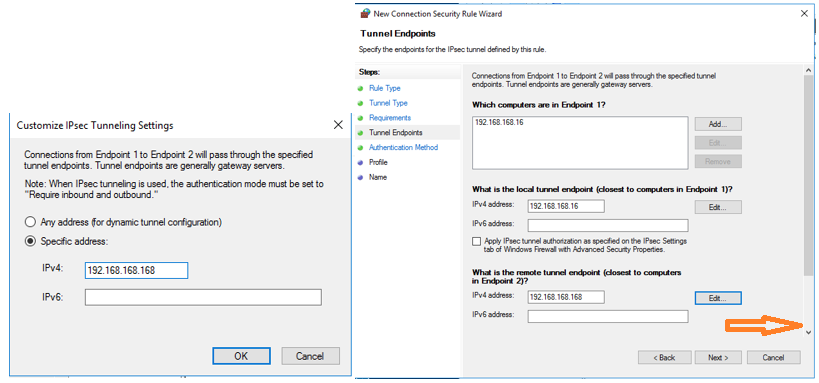
- Then scroll down as indicated by the arrow in the above picture to reveal the last part of the Tunnel Endpoints configuration
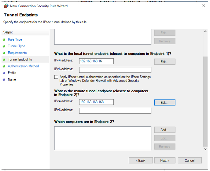
In “Which computers are in Endpoint 2?" click on “Add…” and enter the X0 Subnet : 192.168.168.0/24. Click “OK”.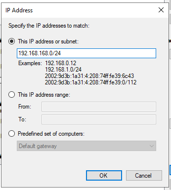
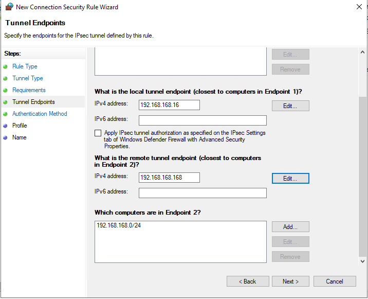
- Click on “Next >”
- On the Authentication Method screen, select “Advanced”, and click “Customize…”.
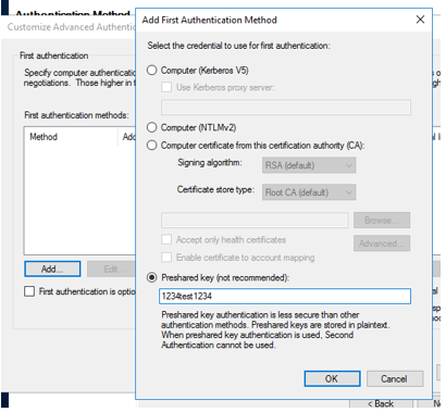
- Under “First authentication methods”, click “Add…”.
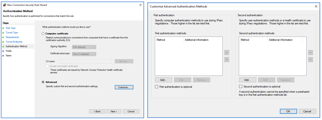
- On the "Add First Authentication Method" window, select the “Preshared key” option, and enter a preshared key that will also be used on the firewall’s VPN Policy later the setup. In this example the Preshared key is 1234test1234 Click “OK”. Click “OK” again to go back to the Authentication Method screen. Click “Next”
.
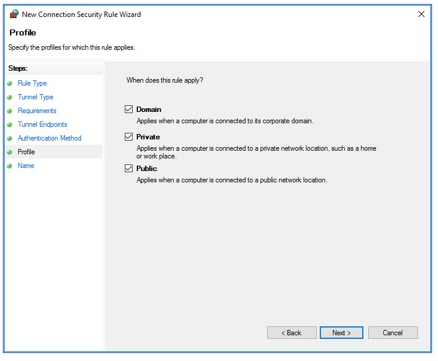
- On the Profile screen, check all the boxes and click “Next”. On the Name screen, provide a name for the new rule and optionally provide a description. Click “Finish”.
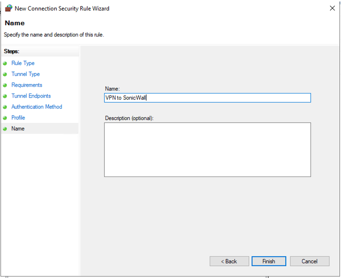
Back on the Windows Firewall with Advanced Security window you’ll now see the Connection Security Rule that was just created.
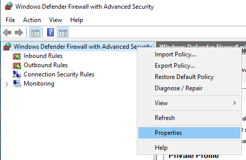
- Right-click on “Windows Firewall with Advanced Security” on the left panel. Select “Properties”.
- Click on the “IPsec Settings” tab. Under “IPsec exemptions” on “Exempt ICMP from IPsec” Select "YES" and click "Apply"
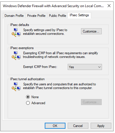
- Under “IPsec defaults” click “Customize…”
- On the Customize IPsec Defaults window, under “Key exchange (Main Mode)” select “Advanced” and click “Customize…”.
There may be pre-defined entries in either list. Select each default Security Method and click on “Remove”. Then click on “Add…”.
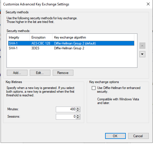
For Integrity algorithm select “SHA-256”. For Encryption algorithm select “AES-CBC 256”. For “Key exchange algorithm” select “Diffie-Hellman Group 14”. Click “OK”.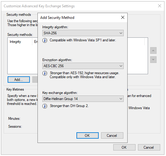
Under “Key lifetimes” enter 480 minutes. Click “OK”.
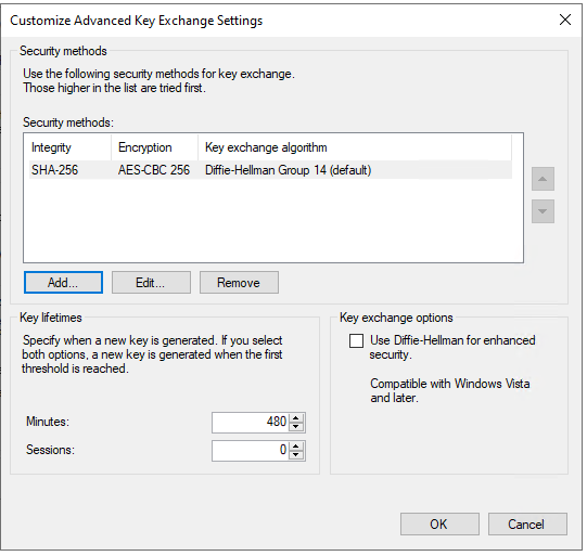
- On the Customize IPsec Defaults window, under “Data protection (Quick Mode)” select “Advanced” and click “Customize…”.
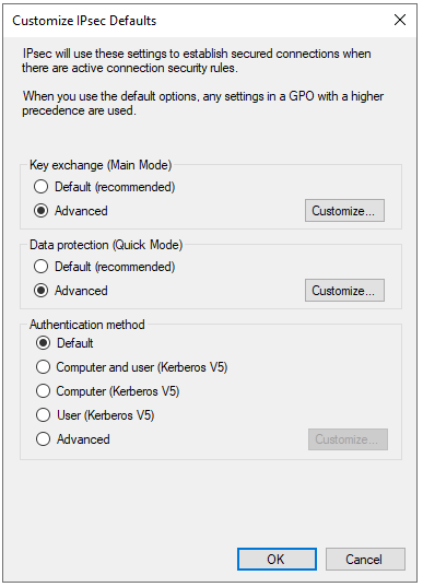
There may be pre-defined entries in either list.
Select each default Security Method and click on “Remove”. Then click on “Add…” starting from "Data integrity algorithms" and then on "Data integrity and encryption"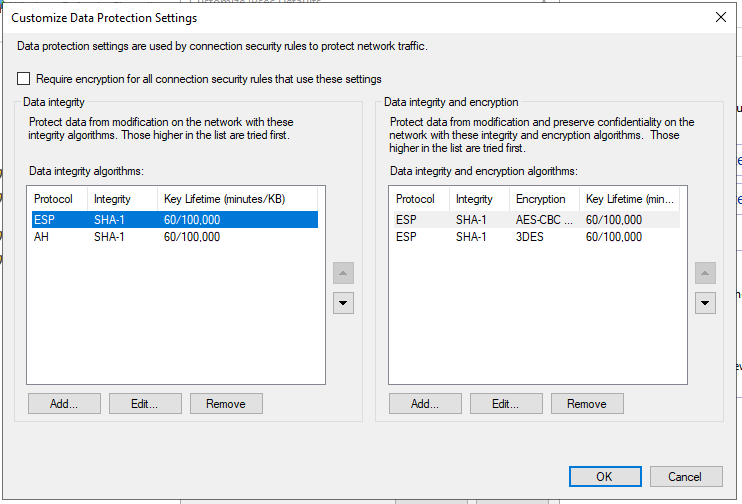
In "Add Integrity Algorithm" configure Protocol ESP - Integrity Algorithm - SHA-256 and set the Key Lifetime to 480 Minutes. Click "OK"
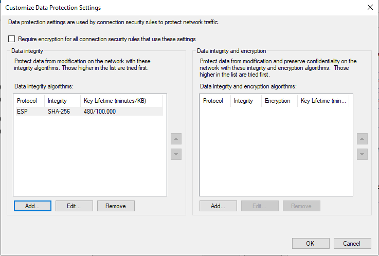
Click on "Add..." under ""Data integrity and encryption"
In "Add Integrity Algorithm" configure Protocol ESP - Integrity Algorithm - AES-CBC-256 - Integrity Algorithm - SHA-256 and set the Key Lifetime to 480 Minutes. Click "OK"
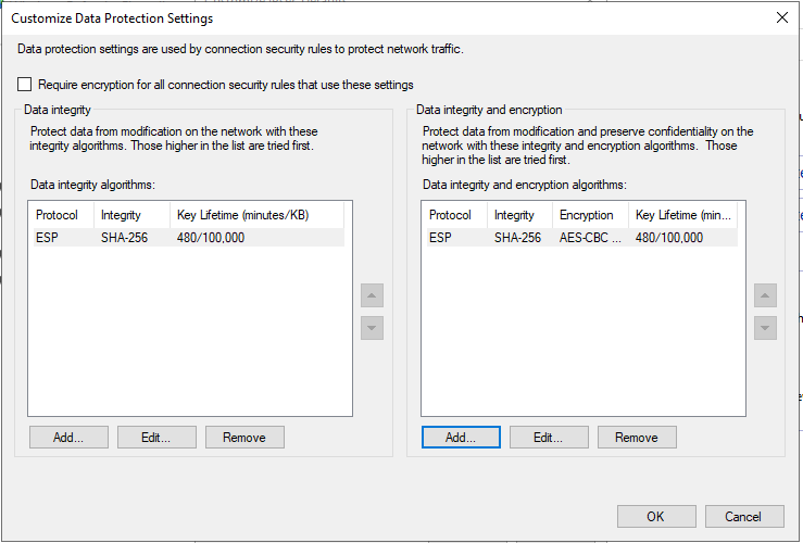
Click "OK" to close the popup and go back to "Customize IPSec Defaults" then click "OK" again to close the popup and again "OK" to close the Windows Firewall Advanced Properties.
FIREWALL CONFIGURATION
Resolution for SonicOS 7.X
This release includes significant user interface changes and many new features that are different from the SonicOS 6.5 and earlier firmware. The below resolution is for customers using SonicOS 7.X firmware.
- On the firewall’s Management UI, navigate to Objects | Addresses.
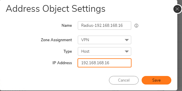
- Click the Address Objects tab. Click the Add button to create a new Host Type Address Object in the VPN Zone with the IP address of the Windows server. In this example, 192.168.168.16. Click Save.
- On the firewall’s Management UI, navigate to NETWORK | IPSec VPN | Rules and Settings.
Click the + Add button. - VPN Policy configuration:
- General tab
- Policy Type: “Site to Site”.
- Authentication Method: “IKE using Preshared Secret”.
- Enter a name for the VPN Policy. In this example, I entered To Radius
- Enter the server’s IP address into the “IPsec Primary Gateway Name or Address” In this example, 192.168.168.16 (Windows Server IP Address)
- Enter the preshared key configured earlier on the server. In this example it was 1234test1234
If the “Mask Shared Secret” checkbox is enabled, confirm the shared secret. I’ve disabled that option to display the key for this example.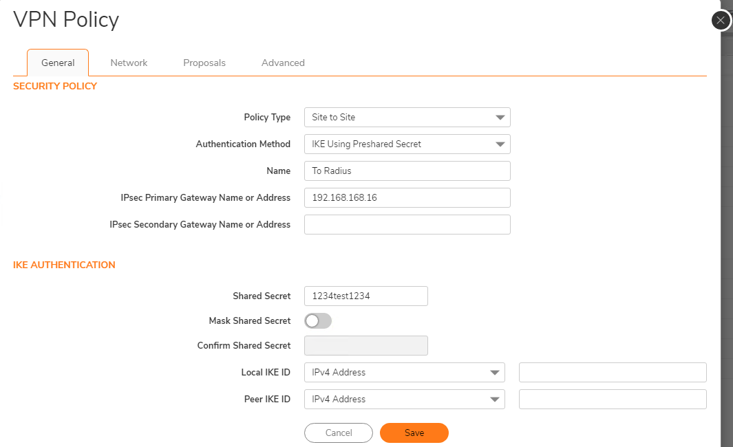
Network tab
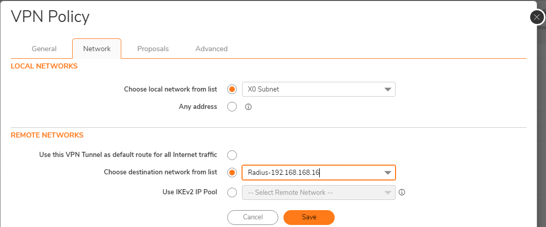
- Select “Choose local network from list” and choose “X0 Subnet” from the list.
- Select “Choose destination network from list” and choose the new object created for the Windows server. In this example, “Radius-192.168.168.16”
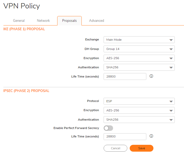
Proposals tab
Phase 1 IKE Proposals
Exchange: “Main Mode”
- DH Group: “Group 14”
- Encryption: “AES-256”
- Authentication: “SHA256”
- Life Time (seconds): “28800"
Phase 2 IPSec Proposals
- Protocol: “ESP”
- Encryption: “AES-256”
- Leave Perfect Forward Secrecy disabled (default)
- Authentication: SHA256
- Life Time (seconds): “28800”
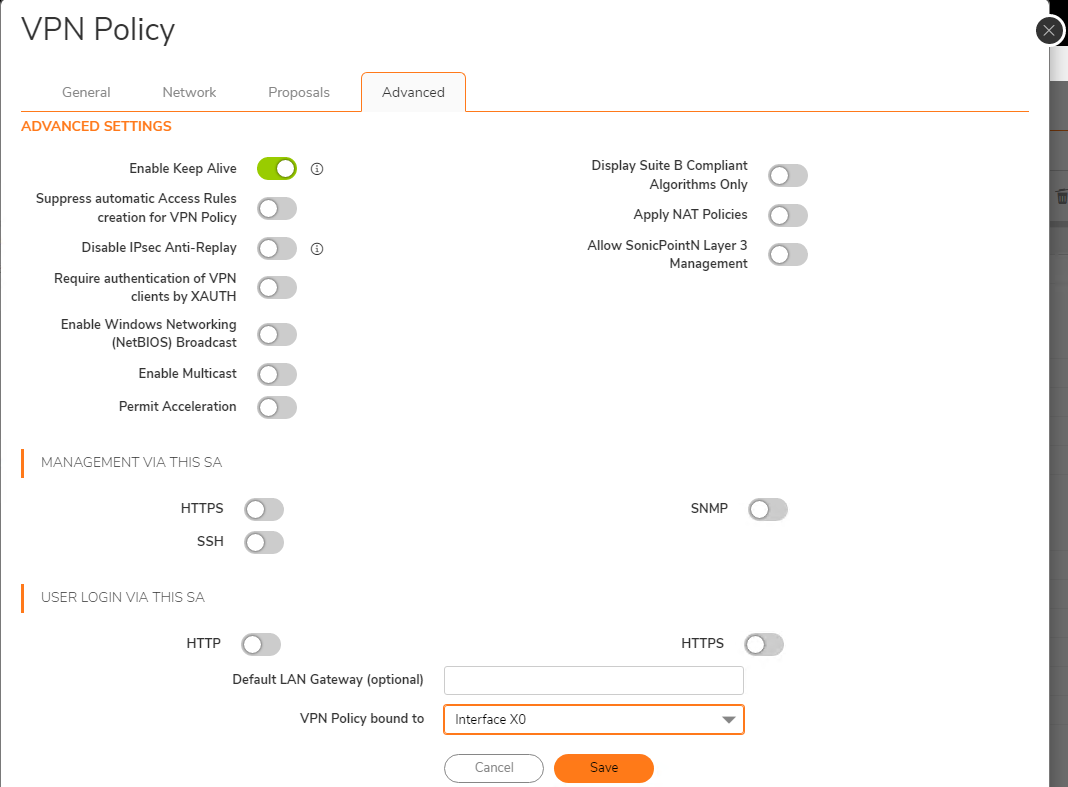
Advanced tab
- Enable/check the “Enable Keep Alive”
- Set the “VPN Policy bound to” dropdown to the interface where the Windows server resides. In this example, the X0 interface:
- Click Save.
- VPN Tunnel should go up, as indicated by the green dot.

"Active Tunnel" tab will show the networks included in the VPN tunnel
"System Logs" will show the logs related to the VPN tunnel.
On Windows Server the Monitoring section on Windows Firewall will show the VPN SAs for both Phase 1 (Main Mode) and Phase 2 (Quick Mode).

The traffic between the firewall and the Radius server is now encrypted.
Testing the Radius Connectivity: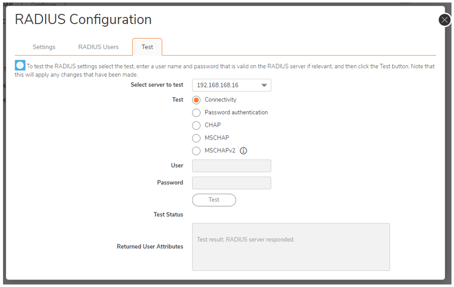

Traffic is encrypted with ESP protocols, packets to radius are reported in clear (in the above screenshot packet #4 and #8) because since the Monitor Filter is capturing the UDP Protocol, the SonicWall is reporting the traffic identified on the capture.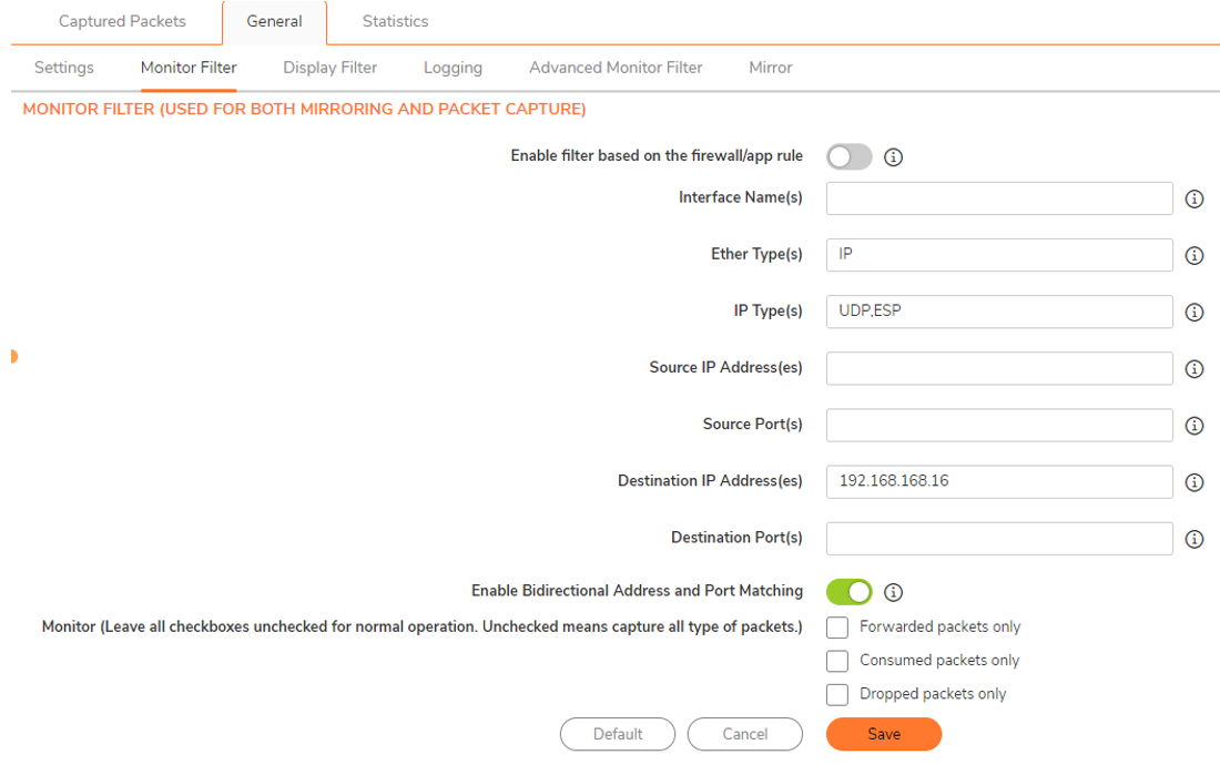
On Windows Server, If Windows Firewall Logs are enabled the RADIUS connection TEST is reported
Related Articles
- Error:"Invalid API Argument" when modifying the access rules
- Cysurance Partner FAQ
- Configure probe monitoring for WAN Failover and Loadbalancing - SonicWall UTM


 YES
YES NO
NO