-
Products
-
SonicPlatform
SonicPlatform is the cybersecurity platform purpose-built for MSPs, making managing complex security environments among multiple tenants easy and streamlined.
Discover More
-
-
Solutions
-
Federal
Protect Federal Agencies and Networks with scalable, purpose-built cybersecurity solutions
Learn MoreFederalProtect Federal Agencies and Networks with scalable, purpose-built cybersecurity solutions
Learn More - Industries
- Use Cases
-
-
Partners
-
Partner Portal
Access to deal registration, MDF, sales and marketing tools, training and more
Learn MorePartner PortalAccess to deal registration, MDF, sales and marketing tools, training and more
Learn More - SonicWall Partners
- Partner Resources
-
-
Support
-
Support Portal
Find answers to your questions by searching across our knowledge base, community, technical documentation and video tutorials
Learn MoreSupport PortalFind answers to your questions by searching across our knowledge base, community, technical documentation and video tutorials
Learn More - Support
- Resources
- Capture Labs
-
- Company
- Contact Us
How to deploy SonicWall switches when SonicWall UTM is in High availability mode?


Description
This KB explains how SonicWall switches can be deployed with the SonicWall UTM devices in high availability mode.
The switches can be deployed with one or two dedicated uplinks and also with common uplinks. Currently, daisy chain switch mode is not supported.
Resolution
Configuring HA and PortShields With Dedicated Uplink(s)
 NOTE: To use the switch with HA, you must first deploy the firewalls in high availability, and then add the switch.
 CAUTION: The auto-authorize option cannot be used while the firewall is in HA.
There are two ways to configure HA units with dedicated uplinks:
- Configuring HA Using One Switch Management Port
- Configuring HA Using Two Switch Management Ports
Configuring HA Using One Switch Management Port
In this configuration with PortShield functionality in HA mode, firewall interfaces that serve as PortShield hosts should be connected to the switch on active and standby units. The PortShield members should also be connected to ports on the switch. The link between the firewall interface serving as the PortShield host and the switch is set up as a dedicated uplink.
HA Pair Using One Switch Management Port Topology shows a firewall HA pair with a switch and one dedicated link:
• The firewall interfaces, X3 and X4, on the primary unit are connected to ports 12 and 13 on the switch.
• X3 and X4 are configured as PortShield hosts.
• Similarly, the firewall interfaces X3 and X4 on the secondary unit are connected to ports 14 and 15 on the switch.
• Ports 12 and 14 on the switch are port shielded to X3 with the dedicated uplink option enabled.
• Ports 13 and 15 on the switch are port shielded to X4 with the dedicated uplink option enabled.
• Ports 2 and 4 are port shielded to X3.
• Ports 3 and 5 are port shielded to X4.
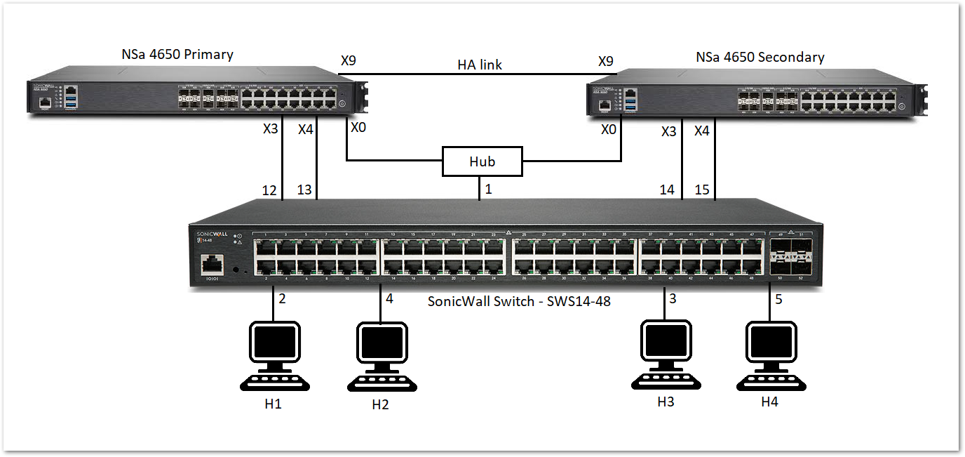
When the primary unit is in Active HA mode, traffic between H1 and X3 is carried over the dedicated link between X3 and 12, and traffic between H3 and X4 is carried over the dedicated link between X4 and 13.
When the secondary unit is in Active HA mode, traffic between H1 and X3 is carried over the dedicated link between X3 and 14, and traffic between H3 and X4 is carried over the dedicated link between X4 and 15.
The link between the firewall interface, X0, and port 1 on the switch, carries the management traffic to manage the switch from the firewall. In such a configuration, X0 is configured to be in the same subnet as the switch. Also, X0 on the primary as well as the secondary is ensured to be connected to port 1 of the switch (for example, via a hub) so that when the secondary firewall becomes the active unit, the switch can be managed via the link
between the firewall interface X0 on the secondary and port 1 of the switch. In such a configuration, when the switch is provisioned, the Primary Switch Management and Secondary Switch Management are set to 1.
To set up HA with one dedicated uplink
- Navigate to MANAGE | Switch Controller | Overview tab. Under Physical View, click on the Add switch button.
 TIP: For SonicOS 7.X, navigate to DEVICE | EXTERNAL CONTROLLERS | Switch Network | Overview. Under the List View tab, click on the Add switch button.
 - Fill in all necessary information like Serial number, IP address, username, password.
- Select the primary and secondary management uplink as 1.
- Select the firewall uplink as Interface X0.
- Select the primary and secondary switch uplink as 1.
- Click on Add.
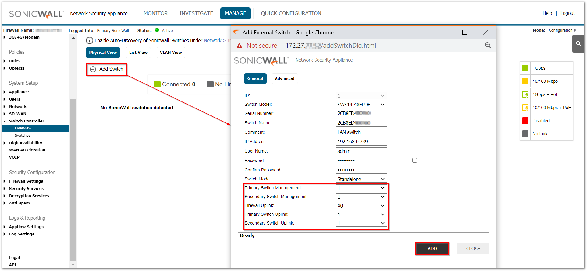
 NOTE: The Firewall Uplink and Switch Uplink options are set the same in this configuration to support the redundant firewalls.
Configuring HA Using Two Switch Management Ports
You can connect X0 of the primary and secondary firewalls directly to the ports on the switch. In this case, two switch ports are used on the switch for management traffic.
HA Pair Using 2 Switch Management Ports Topology shows a firewall HA pair with a switch and two dedicated links:
• X0 of the primary unit is connected to port 1.
• X0 of the secondary unit is connected to port 7.
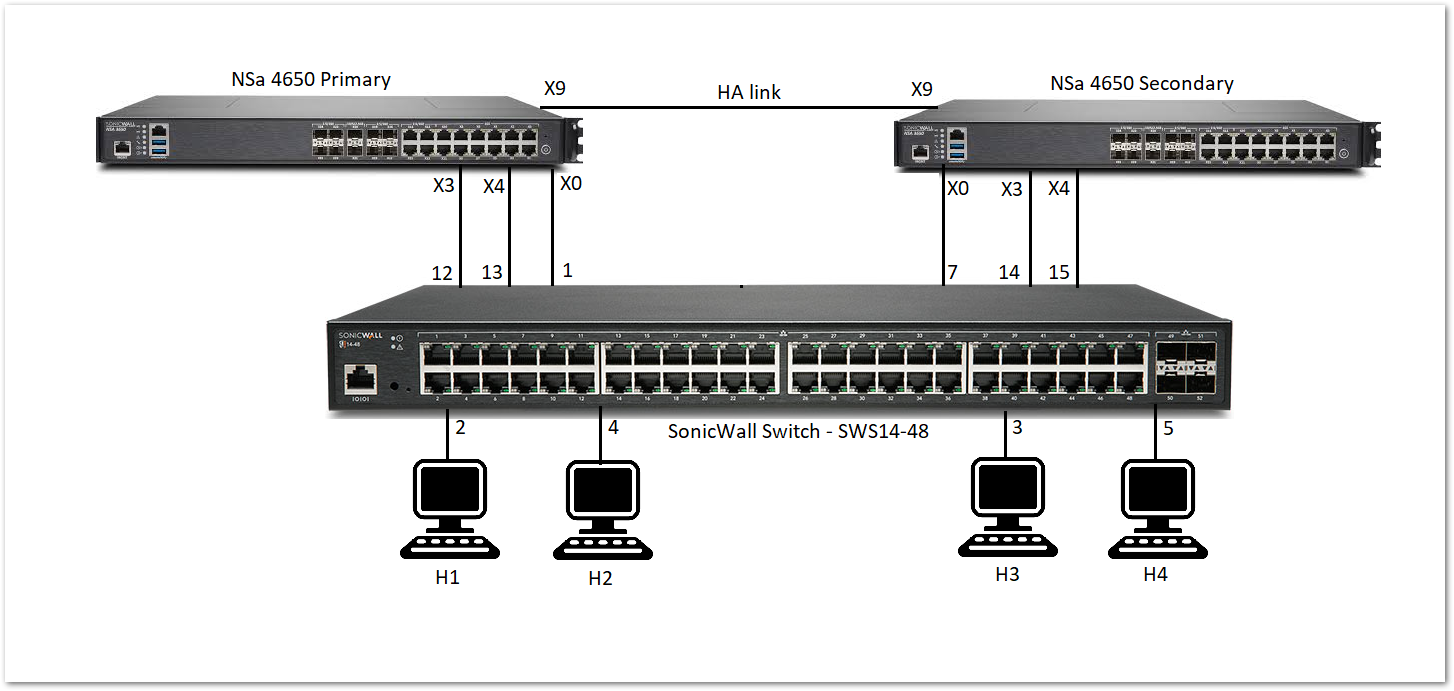
When the primary firewall is active, the link between X0 of the primary and port 1 of the switch carries the management traffic. When the secondary firewall is active, the link between X0 of the secondary and port 7 of the switch is used by the firewall to manage the switch.
To set up HA with two switch management ports
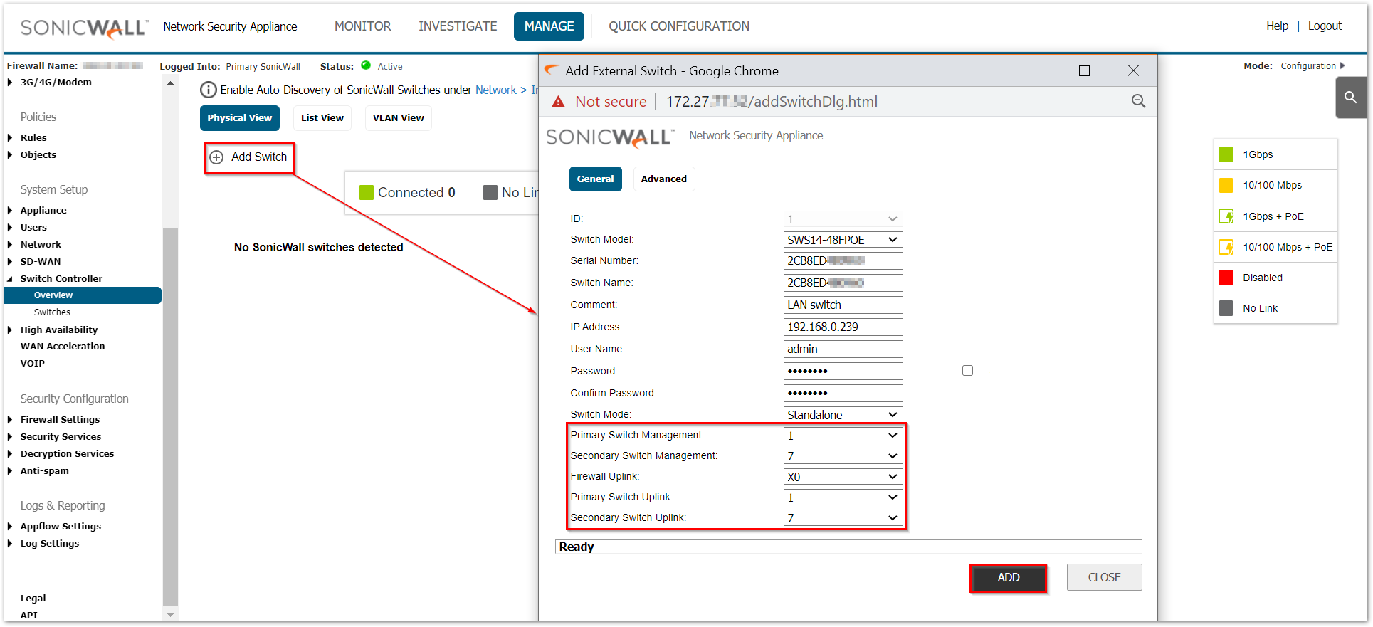
- Navigate to MANAGE | Switch Controller | Overview tab. Under Physical View, click on the Add switch button.
 TIP: For SonicOS 7.X, navigate to DEVICE | EXTERNAL CONTROLLERS | Switch Network | Overview. Under the List View tab, click on the Add switch button.
 - Fill in all necessary information like Serial number, IP address, username, password.
- Select the primary management uplink and primary switch uplink as 1.
- Select the secondary management uplink and secondary switch uplink as 7.
- Select the firewall uplink as Interface X0.
- Click on Add.
Configuring HA and PortShield With a Common Uplink
In this configuration with PortShield functionality in HA mode, a link between the active/standby firewalls and the switch serves as a common uplink to carry all the port shielded traffic. Firewall interfaces that serve as PortShield hosts are connected to a separate switch (not necessarily a switch) and not the same switch connected to the active and standby units. This other switch avoids the looping of packets for the same PortShield VLAN. The PortShield members can be connected to ports on the switch that is controlled by the active/standby firewalls.
HA Pair Using a Common Switch Topology shows a firewall pair and two switches. The link between X3 and Switch 1 is set up as a common uplink. Similarly, the link between X2 and Switch 2 is set up as a common uplink. The PortShield hosts X0 are connected to a different switch (which could be a SonicWall switch or any other vendor’s switch) to avoid looping of packets. Ports 10 on both Switch 1 and Switch 2 are portshielded to X0, and hosts connected to Ports 10 on both switches can communicate using the common uplink.
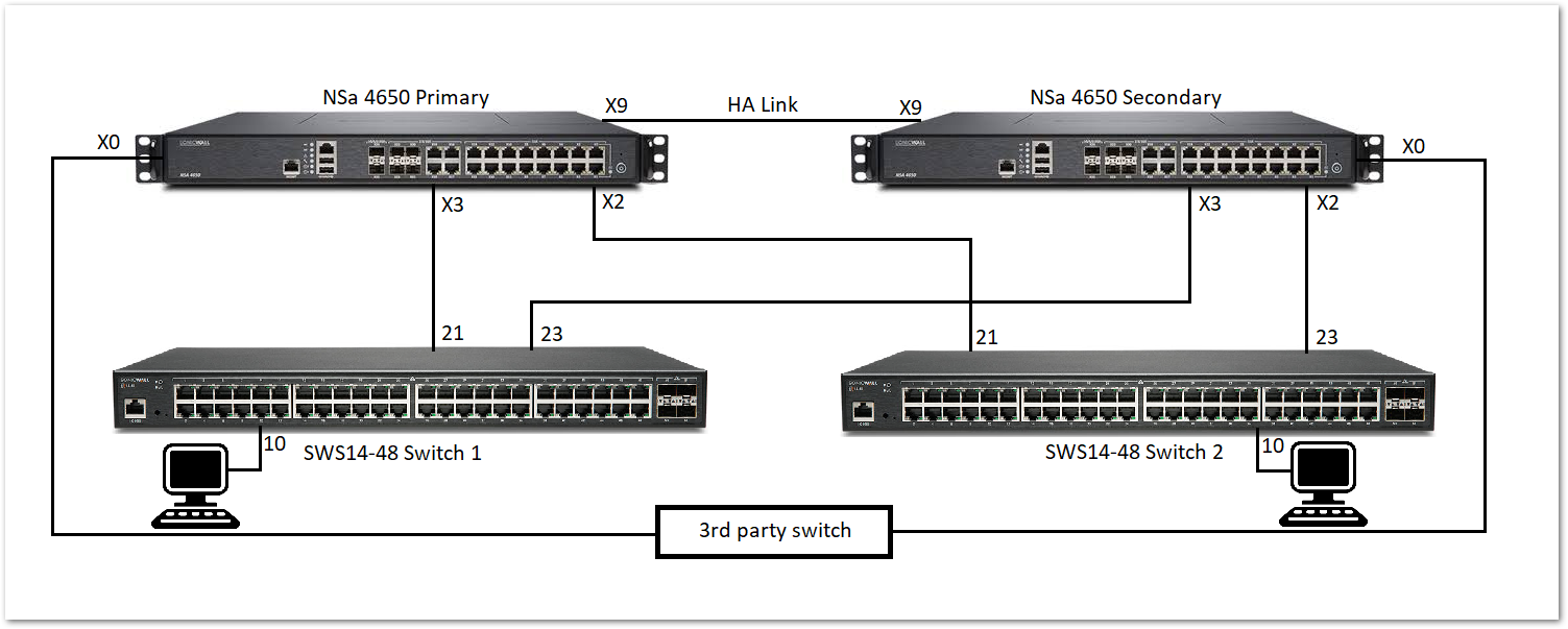
To set up HA with a common uplink:
For switch 1:
- Navigate to MANAGE | Switch Controller | Overview tab. Under Physical View, click on the Add switch button.
 TIP: For SonicOS 7.X, navigate to DEVICE | EXTERNAL CONTROLLERS | Switch Network | Overview. Under the List View tab, click on the Add switch button.
 - Fill in all necessary information like Serial number, IP address, username, password.
- Select the primary and secondary management uplink as 21.
- Select the firewall uplink as Interface X3.
- Select the primary and secondary switch uplink as 23.
- Click on Add.
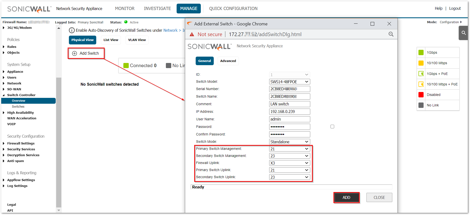
For switch 2:
- Navigate to MANAGE | Switch Controller | Overview tab. Under Physical View, click on the Add switch button.
 TIP: For SonicOS 7.X, navigate to DEVICE | EXTERNAL CONTROLLERS | Switch Network | Overview. Under the List View tab, click on the Add switch button.
 - Fill in all necessary information like Serial number, IP address, username, password.
- Select the primary and secondary management uplink as 21.
- Select the firewall uplink as Interface X2.
- Select the primary and secondary switch uplink as 23.
- Click on Add.
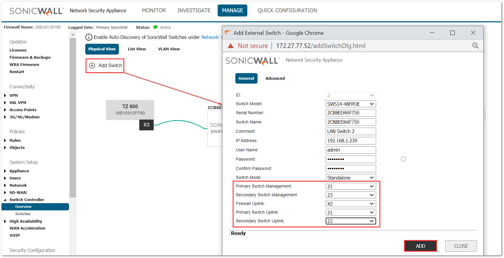
Related Articles
- Supported SonicWall and 3rd party SFP and SFP+ Modules that can be used with SonicWall Switches
- How to enable Port Mirror on Sonicwall Switch.
- Create a new VLAN on Sonicwall Switch managed by WCM.


 YES
YES NO
NO