-
Products
-
SonicPlatform
SonicPlatform is the cybersecurity platform purpose-built for MSPs, making managing complex security environments among multiple tenants easy and streamlined.
Discover More
-
-
Solutions
-
Federal
Protect Federal Agencies and Networks with scalable, purpose-built cybersecurity solutions
Learn MoreFederalProtect Federal Agencies and Networks with scalable, purpose-built cybersecurity solutions
Learn More - Industries
- Use Cases
-
-
Partners
-
Partner Portal
Access to deal registration, MDF, sales and marketing tools, training and more
Learn MorePartner PortalAccess to deal registration, MDF, sales and marketing tools, training and more
Learn More - SonicWall Partners
- Partner Resources
-
-
Support
-
Support Portal
Find answers to your questions by searching across our knowledge base, community, technical documentation and video tutorials
Learn MoreSupport PortalFind answers to your questions by searching across our knowledge base, community, technical documentation and video tutorials
Learn More - Support
- Resources
- Capture Labs
-
- Company
- Contact Us
How do I create a GRE 4to6 tunnel?


Description
This article covers how to create a GRE 4to6 tunnel using a SonicWall firewall.
Resolution
Resolution for SonicOS 7.X
This release includes significant user interface changes and many new features that are different from the SonicOS 6.5 and earlier firmware. The below resolution is for customers using SonicOS 7.X firmware.
To create a GRE 4to6 tunnel please perform the following:
- Login to the firewall as an administrator.
- Navigate to Network | System | Interfaces. Ensure that IPv4 is selected under Interface settings.
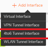
- Select the drop down “Add Interface” and choose “4to6 Tunnel Interface”.
- A new tab will open. Under “Tunnel Type:” select GRE 4to6 Tunnel, On General Tab:
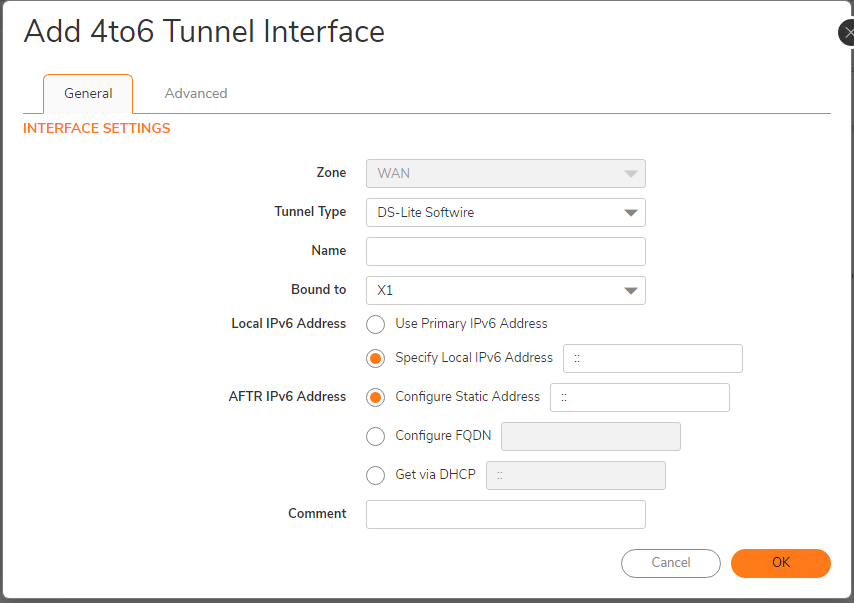
- Zone – Interface zone. It should be WAN zone, and can not be edited.
- Name – Interface name. It can’t be null and the max length is 25.
- IP Address – Interface IPv4 address.
- Subnet Mask – Subnet mask.
- Bound to – The interface which tunnel is bound to. It should be a physical WAN interface. If Bound Interface is link down, the GRE 4to6 Tunnel will be down as well. Bound Interface can not change its zone to others.
- Local IPv6 address – As an interface may have various IPv6 addresses, there are two modes for the local IPv6 address choice.
- Using bound Interface’s IPv6 Address as Local Address. When bound interface is on DHCPv6 or Autonomous Mode, it would get a dynamic IP (DHCPv6 IP or Autonomous IP) as tunnel local IPv6 address, and DHCP IP has a higher priority. Otherwise, if bound interface is on STATIC or other Mode, it would use primary static v6 IP as tunnel local IPv6 address. If bound interface IP is released/deleted, it can be ::.
- Specify the Local IPv6 Address.
- Remote IPv6 address – the endpoints must be specified.
- Next, click the Advanced tab:
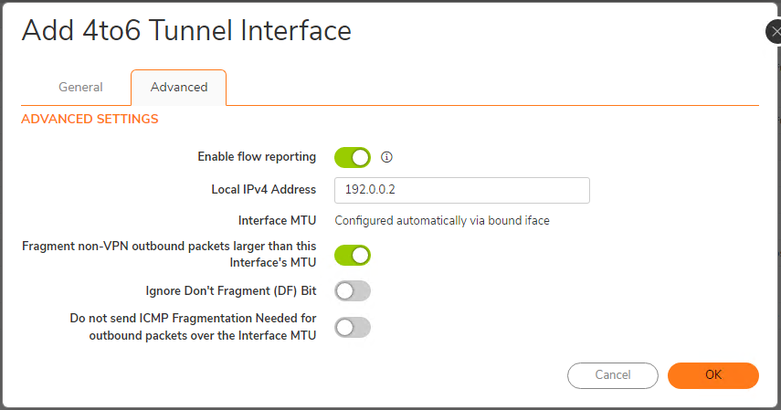
a. MTU – the MTU effective for IPv4 packet size before encapsulation. GRE tunnel will automatically calculate its MTU based on the bound interface’s IPv6 MTU. When bound IPv6 interface MTU changes, the existed tunnel’s MTU will be automatically updated. This is the default configuration.Gre_4to6_tun_mtu = bound_if_mtu – IPv6_header_length – GRE_header_length
b. Like a WAN interface, there are three configuration items for fragmentation setting over a GRE 4to6 Tunnel interface:
Fragment non-VPN outbound packets larger than this Interface's MTU (default enabled)
Ignore Don't Fragment (DF) Bit
Suppress ICMP Fragmentation Needed message generation
Configuring Route Entry:
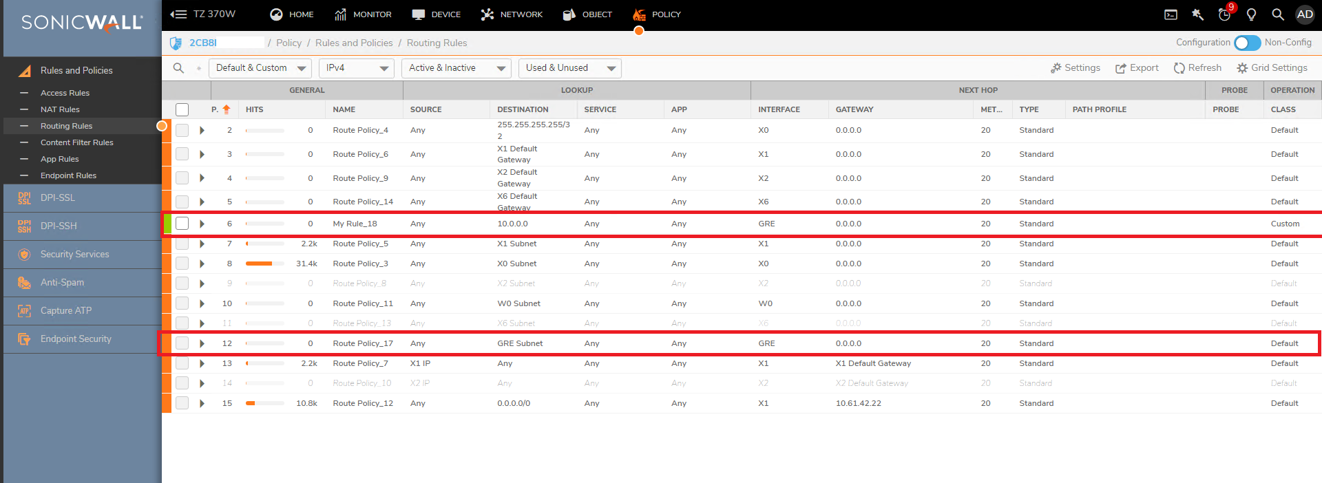
When a GRE tunnel is configured, it can be selected as the egress interface of an IPv4 route entry. If we want to route IPv4 traffic over the GRE tunnel interface, we can manually add an IPv4 route entry (for example, entry 6 in the below figure).
GRE tunnels are also like a general interface. When adding a new GRE tunnel interface, it will auto-add a route policy (for example, entry 12 the in below figure).
Auto Address objects:
When adding a GRE tunnel interface, it will create two Address Objects with name “NAME IP” and “NAME Subnet”, and “NAME IP” will be added to “All Interface IP” group, and “Zone Interface IP” group. “NAME Subnet” will be added to “Zone Subnets”.
When the interface is deleted, the address objects will be deleted.

Resolution for SonicOS 6.5
This release includes significant user interface changes and many new features that are different from the SonicOS 6.2 and earlier firmware. The below resolution is for customers using SonicOS 6.5 firmware.
To create a GRE 4to6 tunnel please perform the following:
- Login to the firewall as an administrator.
- Navigate to MANAGE | Network | Interfaces. Ensure that IPv4 is selected next to "View IP Version".
- Select the drop down “Add Interface” and choose “4to6 Tunnel Interface”.
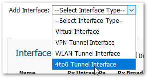
- A pop-up box will open. Under “Tunnel Type:” select GRE 4to6 Tunnel.
- Click the General tab:
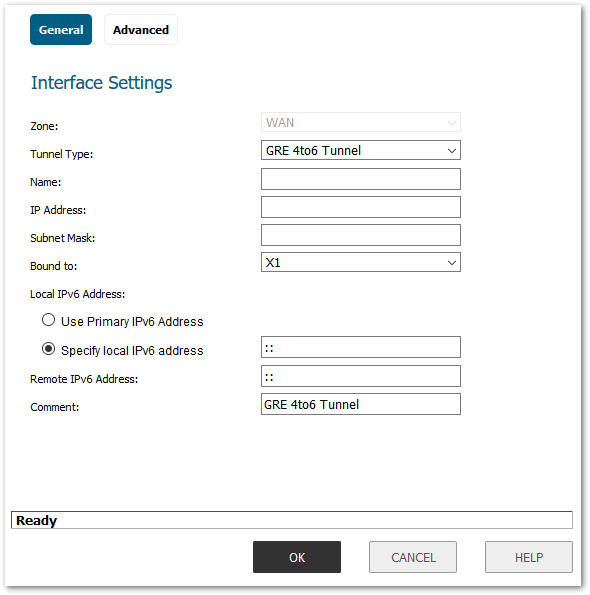
- Zone – Interface zone. It should be WAN zone, and can not be edited.
- Name – Interface name. It can’t be null and the max length is 25.
- IP Address – Interface IPv4 address.
- Subnet Mask – Subnet mask.
- Bound to – The interface which tunnel is bound to. It should be a physical WAN interface. If Bound Interface is link down, the GRE 4to6 Tunnel will be down as well. Bound Interface can not change its zone to others.
- Local IPv6 address – As an interface may have various IPv6 addresses, there are two modes for the local IPv6 address choice.
- Using bound Interface’s IPv6 Address as Local Address. When bound interface is on DHCPv6 or Autonomous Mode, it would get a dynamic IP (DHCPv6 IP or Autonomous IP) as tunnel local IPv6 address, and DHCP IP has a higher priority. Otherwise, if bound interface is on STATIC or other Mode, it would use primary static v6 IP as tunnel local IPv6 address. If bound interface IP is released/deleted, it can be ::.
- Specify the Local IPv6 Address.
- Remote IPv6 address – the endpoints must be specified.
- Next, click the Advanced tab:
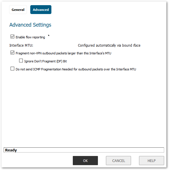
- MTU – the MTU effective for IPv4 packet size before encapsulation. GRE tunnel will automatically calculate its MTU based on the bound interface’s IPv6 MTU. When bound IPv6 interface MTU changes, the existed tunnel’s MTU will be automatically updated. This is the default configuration.
Gre_4to6_tun_mtu = bound_if_mtu – IPv6_header_length – GRE_header_length - Like a WAN interface, there are three configuration items for fragmentation setting over a GRE 4to6 Tunnel interface:
- Fragment non-VPN outbound packets larger than this Interface's MTU (default enabled)
- Ignore Don't Fragment (DF) Bit
- Suppress ICMP Fragmentation Needed message generation
- MTU – the MTU effective for IPv4 packet size before encapsulation. GRE tunnel will automatically calculate its MTU based on the bound interface’s IPv6 MTU. When bound IPv6 interface MTU changes, the existed tunnel’s MTU will be automatically updated. This is the default configuration.
Configuring Route Entry
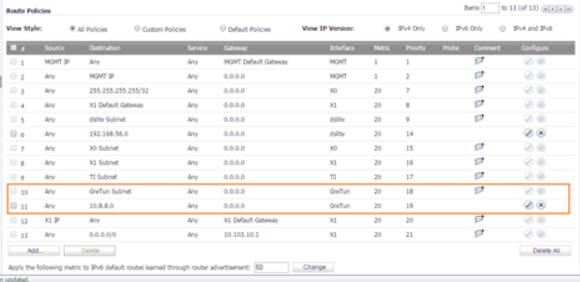
When a GRE tunnel is configured, it can be selected as the egress interface of an IPv4 route entry. If we want to route IPv4 traffic over the GRE tunnel interface, we can manually add an IPv4 route entry (for example, entry 11 in the below figure).
GRE tunnels are also like a general interface. When adding a new GRE tunnel interface, it will auto-add a route policy (for example, entry 10 the in below figure).
Auto Address Objects
When adding a GRE tunnel interface, it will create two Address Objects with name “NAME IP” and “NAME Subnet”, and “NAME IP” will be added to “All Interface IP” group, and “Zone Interface IP” group. “NAME Subnet” will be added to “Zone Subnets”.
When the interface is deleted, the address objects will be deleted.

Related Articles
- Error:"Invalid API Argument" when modifying the access rules
- Cysurance Partner FAQ
- Configure probe monitoring for WAN Failover and Loadbalancing - SonicWall UTM
Categories
- Firewalls > NSa Series > VPN
- Firewalls > TZ Series


 YES
YES NO
NO