-
Products
-
SonicPlatform
SonicPlatform is the cybersecurity platform purpose-built for MSPs, making managing complex security environments among multiple tenants easy and streamlined.
Discover More
-
-
Solutions
-
Federal
Protect Federal Agencies and Networks with scalable, purpose-built cybersecurity solutions
Learn MoreFederalProtect Federal Agencies and Networks with scalable, purpose-built cybersecurity solutions
Learn More - Industries
- Use Cases
-
-
Partners
-
Partner Portal
Access to deal registration, MDF, sales and marketing tools, training and more
Learn MorePartner PortalAccess to deal registration, MDF, sales and marketing tools, training and more
Learn More - SonicWall Partners
- Partner Resources
-
-
Support
-
Support Portal
Find answers to your questions by searching across our knowledge base, community, technical documentation and video tutorials
Learn MoreSupport PortalFind answers to your questions by searching across our knowledge base, community, technical documentation and video tutorials
Learn More - Support
- Resources
- Capture Labs
-
- Company
- Contact Us
Configuring Network Monitor Policies to monitor a network path viability


Description
Configuring Network Monitor Policies to monitor a network path viability.
Resolution
Resolution for SonicOS 7.X
This release includes significant user interface changes and many new features that are different from the SonicOS 6.5 and earlier firmware. The below resolution is for customers using SonicOS 7.X firmware.
The Network in the top navigation menu consists of Network Monitor services which provides a flexible mechanism for monitoring network path viability. The results and status of this monitoring are displayed dynamically on the Network Monitor page, and are also provided to affected client components and logged in the system log.
Each custom NM (Network Probe) policy defines a destination Address Object to be probed. This Address Object may be a Host, Group, Range, or FQDN. When the destination Address Object is a Group, Range or FQDN with multiple resolved addresses, Network Monitor probes each probe target and derives the NM Policy state based on the results.
- Click Network in the top navigation menu.
- Under Network | System | Network Monitor.
- Click Add button to configure network probes policy.
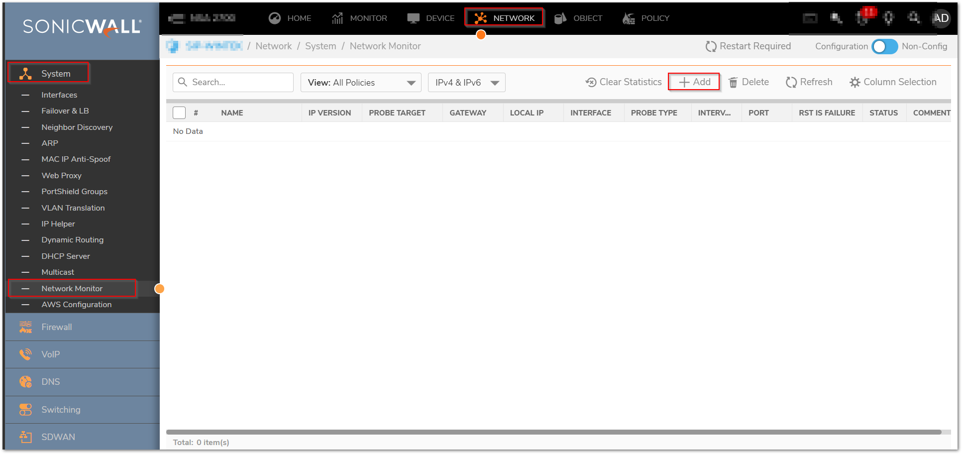
- The Status column elements displays the status of the network connection to the target
- Green indicates that the policy status is UP.
- Red indicates that the policy status is DOWN.
- Yellow indicates that the policy status is UNKNOWN.
You can view details of the probe status by hovering your mouse over the green, red, or yellow light for a policy.
The following information is displayed in the probe status.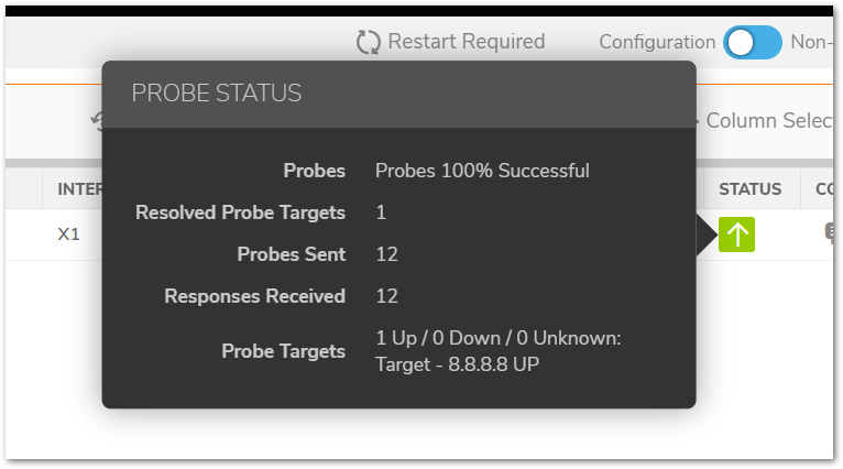
- The percent of successful probes.
- The number of resolved probe targets.
- The total number of probes sent.
- The total number of successful probe responses received.
- A list of resolved probe targets, and their status.
Adding a Network Monitor Policy
To add a network monitor policy on the SonicWall security appliance, perform these steps.
- Click Network in the top navigation menu.
- Click Network | System | Network Monitor.
- Click Add button to configure network probes policy.
- The Add Network Monitor Policy window is displayed.


- Enter the following information to define the network monitor policy.
- Name - Enter a description of the Network Monitor policy.
- Probe Target - Select the Address Object or Address Group to be the target of the policy. Address Objects may be Hosts, Groups, Ranges, or FQDNs object. Objects within a Group object may be Host, Range, or FQDN Address Objects. You can dynamically create a new address object by selecting Create New Address Object.
- Probe Type - Select the appropriate type of probe for the network monitor policy.
- Ping (ICMP) - This probe uses the route table to find the egress interface and next-hop for the defined probe targets. A Ping echo-request is sent out the egress interface with the source IP address of the egress interface. An echo response must return on the same interface within the specified Response Timeout time limit for the ping to be counted as successful.
- TCP - This probe uses the route table to find the egress interface and next-hop for the defined probe targets. A TCP SYN packet is sent to the probe target with the source IP address of the egress interface. A successful response will be counted independently for each probe target when the target responds with either a SYN/ACK or RST via thesame interface within the Response Timeout time window. When a SYN/ACK is received, a RST is sent to close the connection. If a RST is received, no response is returned.
- Ping (ICMP) - Explicit Route - This probe bypasses the route table and uses the source IP address of the interface specified in the Outbound Interface pull down menu to send a Ping to the targets. If a Next Hop Gateway is not specified, the probe assumes that the targets are directly connected to the Outbound Interface's network.
- TCP - Explicit Route - This probe bypasses the route table and uses the source IP address of the interface specified in the Outbound Interface pull down menu to send a TCP SYN packet to the targets. If a Next Hop Gateway is not specified, the probe assumes that the targets are directly connected to the Outbound Interface's network. When a SYN/ACK is received, a RST is sent to close the connection. If a RST is received, no response is returned.
- Next Hop Gateway - Manually specifies the next hop that is used from the outbound interface to reach the probe target. This option must be configured for Explicit Route policies. For non-Explicit Route policies, the probe uses the appliance’s route table to determine the egress interface to reach the probe target. If a Next Hop Gateway is not specified, the probe assumes that the targets are directly connected to the Outbound Interface's network.
- Outbound Interface - Manually specifies which interface is used to send the probe. This option must be configured for Explicit Route policies. For non-Explicit Route policies, the probe uses the appliance’s route table to determine the egress interface to reach the probe target.
- Port - Specifies the destination port of target hosts for TCP probes. A port is not specified for Ping probes.
- Optionally, you can adjust the following thresholds for the probes.
- Probe hosts every - The number of seconds between each probe. This number cannot be less than the Reply time out field.
- Reply time out - The number of seconds the Network Monitor waits for a response for each individual probe before a missed-probe will be counted for the specific probe target. The Reply time out cannot exceed the Probe hosts every field.
- Probe state is set to DOWN after - The number of consecutive missed probes that triggers a host state transition to DOWN.
- Probe state is set to UP after - The number of consecutive successful probes that triggers a host state transition to UP.
- All Hosts Must Respond - Selecting this checkbox specifies that all of the probe target Host States must be UP before the Policy State can transition to UP. If not checked, the Policy State is set to UP when any of the Host States are UP.
- Optionally, you can enter a descriptive comment about the policy in the Comment field.
- Click Add to submit the Network Monitor policy.
EXAMPLE:1
Using Network Monitor Probes in Policy Based Routing
- Network Monitor policy can be used, when configuring a static route, as a condition to dynamically enable or disable the static route. When a Network Monitor policy is used, the static route is dynamically disabled or enabled, based on the state of the probe for the policy.
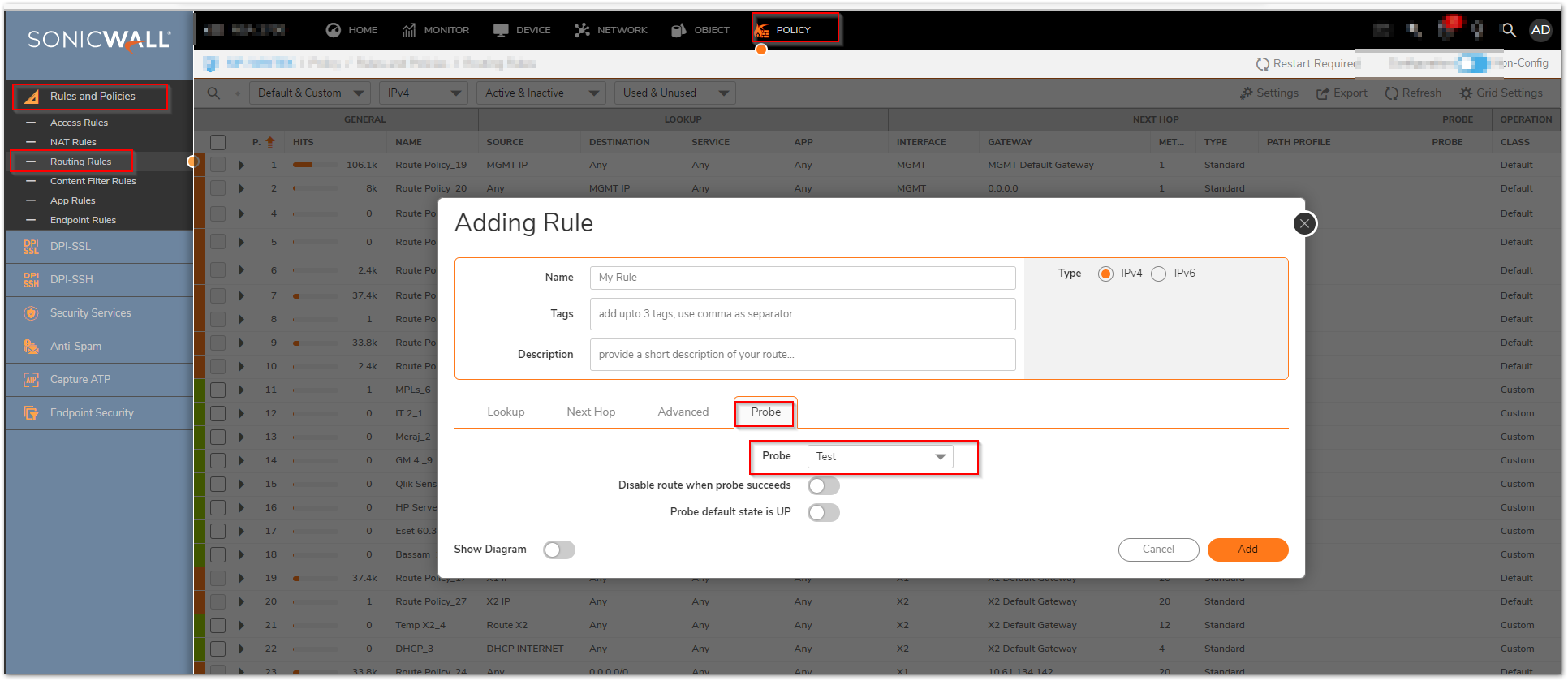
- In the example above, a static route has been created to route traffic to a remote network which is reachable through a router on the LAN. Under the Probe a Network Monitor Policy has been selected which pings a host on the remote network. Failure of the ping will result in disabling this route.
- Typical configurations will not check the Disable route when probe succeeds checkbox, because typically administrators will want to disable a route when a probe to the route’s destination fails. This option is provided to give administrators added flexibility for defining routes and probes.
- The Probe default state is UP option is to have the route consider the probe to be successful (i.e. in the “UP” state) when the attached Network Monitor policy is in the UNKNOWN state. This is useful to control the probe-based behavior when a unit of a High Availability pair transitions from IDLE to ACTIVE, because this transition sets all Network Monitor policy states to UNKNOWN.
Using Network Monitor policies in Route Policies to dynamically Failover between VPN and MPLS connection
- This following article illustrates a scenario wherein two sites with SonicWall UTM devices are connected to each other over a direct connection or an MPLS connection. A site to site VPN connection is defined concurrently between the two sites. The primary connection between the two sites is the direct or the MPLS connection and when it fails, traffic would automatically be routed through a site to site VPN (policy based).
- For detailed instructions please refer to https://www.sonicwall.com/support/knowledge-base/configuring-vpn-Failover-using-static-routes-and-network-monitor-probes/170504720505274/.
Here is a sample log message when the Network Monitoring probe goes Down.
- Click Monitor in the top navigation menu.
- Click Logs | System Logs.

Resolution for SonicOS 6.5
This release includes significant user interface changes and many new features that are different from the SonicOS 6.2 and earlier firmware. The below resolution is for customers using SonicOS 6.5 firmware.
The Investigate in the top navigation menu Under Network Probes page provides a flexible mechanism for monitoring network path viability. The results and status of this monitoring are displayed dynamically on the Network Probes page, and are also provided to affected client components and logged in the system log.
Each custom NM (Network Probe) policy defines a destination Address Object to be probed. This Address Object may be a Host, Group, Range, or FQDN. When the destination Address Object is a Group, Range or FQDN with multiple resolved addresses, Network Monitor probes each probe target and derives the NM Policy state based on the results.
- Click Investigate in the top navigation menu.
- Click Network Probes.
- Click configure button to configure network probes policy.
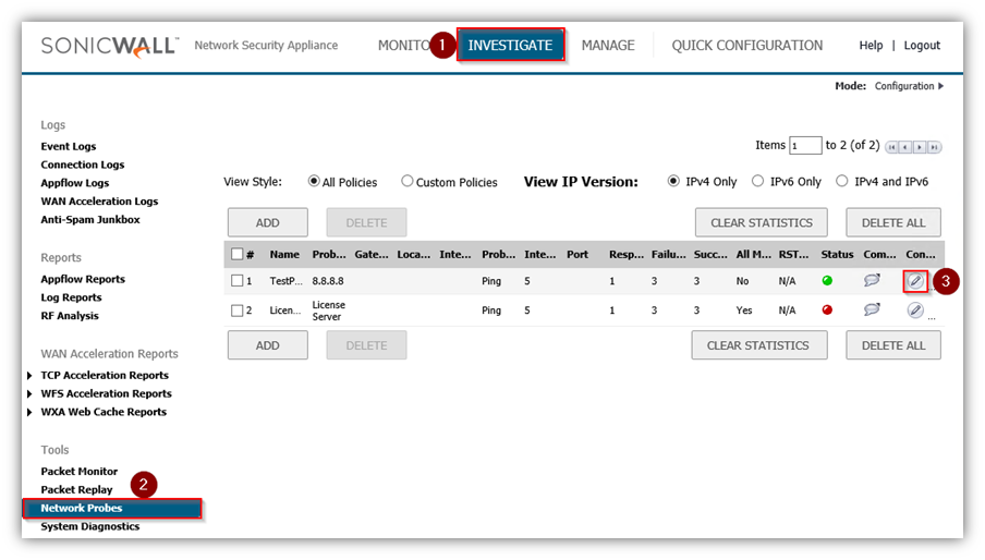
- The Status column elements displays the status of the network connection to the target.
- Green indicates that the policy status is UP.
- Red indicates that the policy status is DOWN.
- Yellow indicates that the policy status is UNKNOWN.
You can view details of the probe status by hovering your mouse over the green, red, or yellow light for a policy.
The following information is displayed in the probe status.
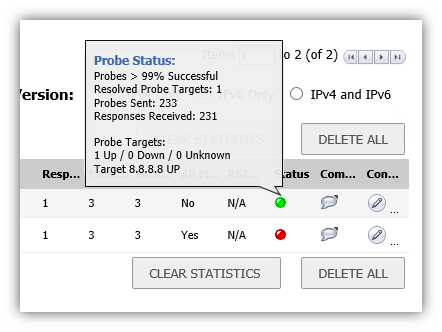
- The percent of successful probes.
- The number of resolved probe targets.
- The total number of probes sent.
- The total number of successful probe responses received.
- A list of resolved probe targets, and their status.
Adding a Network Monitor Policy
To add a network monitor policy on the SonicWall security appliance, perform these steps.
- Click Investigate in the top navigation menu.
- Click Network Probes.
- Click configure button to configure network probes policy.
- The Add Network Monitor Policy window is displayed.
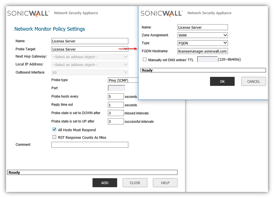
- Enter the following information to define the network monitor policy.
- Name - Enter a description of the Network Monitor policy.
- Probe Target - Select the Address Object or Address Group to be the target of the policy. Address Objects may be Hosts, Groups, Ranges, or FQDNs object. Objects within a Group object may be Host, Range, or FQDN Address Objects. You can dynamically create a new address object by selecting Create New Address Object.
- Probe Type - Select the appropriate type of probe for the network monitor policy.
- Ping (ICMP) - This probe uses the route table to find the egress interface and next-hop for the defined probe targets. A Ping echo-request is sent out the egress interface with the source IP address of the egress interface. An echo response must return on the same interface within the specified Response Timeout time limit for the ping to be counted as successful.
- TCP - This probe uses the route table to find the egress interface and next-hop for the defined probe targets. A TCP SYN packet is sent to the probe target with the source IP address of the egress interface. A successful response will be counted independently for each probe target when the target responds with either a SYN/ACK or RST via thesame interface within the Response Timeout time window. When a SYN/ACK is received, a RST is sent to close the connection. If a RST is received, no response is returned.
- Ping (ICMP) - Explicit Route - This probe bypasses the route table and uses the source IP address of the interface specified in the Outbound Interface pull down menu to send a Ping to the targets. If a Next Hop Gateway is not specified, the probe assumes that the targets are directly connected to the Outbound Interface's network.
- TCP - Explicit Route - This probe bypasses the route table and uses the source IP address of the interface specified in the Outbound Interface pull down menu to send a TCP SYN packet to the targets. If a Next Hop Gateway is not specified, the probe assumes that the targets are directly connected to the Outbound Interface's network. When a SYN/ACK is received, a RST is sent to close the connection. If a RST is received, no response is returned.
- Next Hop Gateway - Manually specifies the next hop that is used from the outbound interface to reach the probe target. This option must be configured for Explicit Route policies. For non-Explicit Route policies, the probe uses the appliance’s route table to determine the egress interface to reach the probe target. If a Next Hop Gateway is not specified, the probe assumes that the targets are directly connected to the Outbound Interface's network.
- Outbound Interface - Manually specifies which interface is used to send the probe. This option must be configured for Explicit Route policies. For non-Explicit Route policies, the probe uses the appliance’s route table to determine the egress interface to reach the probe target.
- Port - Specifies the destination port of target hosts for TCP probes. A port is not specified for Ping probes.
- Optionally, you can adjust the following thresholds for the probes.
- Probe hosts every - The number of seconds between each probe. This number cannot be less than the Reply time out field.
- Reply time out - The number of seconds the Network Monitor waits for a response for each individual probe before a missed-probe will be counted for the specific probe target. The Reply time out cannot exceed the Probe hosts every field.
- Probe state is set to DOWN after - The number of consecutive missed probes that triggers a host state transition to DOWN.
- Probe state is set to UP after - The number of consecutive successful probes that triggers a host state transition to UP.
- All Hosts Must Respond - Selecting this checkbox specifies that all of the probe target Host States must be UP before the Policy State can transition to UP. If not checked, the Policy State is set to UP when any of the Host States are UP.
- Optionally, you can enter a descriptive comment about the policy in the Comment field.
- Click Add to submit the Network Monitor policy.
 EXAMPLE:1
Using Network Monitor Probes in Policy Based Routing
- Network Monitor policy can be used, when configuring a static route, as a condition to dynamically enable or disable the static route. When a Network Monitor policy is used, the static route is dynamically disabled or enabled, based on the state of the probe for the policy.
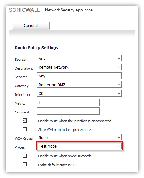
- In the example above, a static route has been created to route traffic to a remote network which is reachable through a router on the DMZ. Under the Probe a Network Monitor Policy has been selected which pings a host on the remote network. Failure of the ping will result in disabling this route.
- Typical configurations will not check the Disable route when probe succeeds checkbox, because typically administrators will want to disable a route when a probe to the route’s destination fails. This option is provided to give administrators added flexibility for defining routes and probes.
- The Probe default state is UP option is to have the route consider the probe to be successful (i.e. in the “UP” state) when the attached Network Monitor policy is in the UNKNOWN state. This is useful to control the probe-based behavior when a unit of a High Availability pair transitions from IDLE to ACTIVE, because this transition sets all Network Monitor policy states to UNKNOWN.
 EXAMPLE: 2
Using Network Monitor policies in Route Policies to dynamically Failover between VPN and MPLS connection
- This following article illustrates a scenario wherein two sites with SonicWall UTM devices are connected to each other over a direct connection or an MPLS connection. A site to site VPN connection is defined concurrently between the two sites. The primary connection between the two sites is the direct or the MPLS connection and when it fails, traffic would automatically be routed through a site to site VPN (policy based).
- For detailed instructions please refer to https://www.sonicwall.com/support/knowledge-base/configuring-vpn-Failover-using-static-routes-and-network-monitor-probes/170504720505274/.
Logs messages
Here is a sample log message when the Network Monitoring probe goes Down.
- Click Investigate in the top navigation menu.
- Click Event Logs.

Resolution for SonicOS 6.2 and Below
The below resolution is for customers using SonicOS 6.2 and earlier firmware. For firewalls that are generation 6 and newer we suggest to upgrade to the latest general release of SonicOS 6.5 firmware.
The Network | Network Monitor page provides a flexible mechanism for monitoring network path viability. The results and status of this monitoring are displayed dynamically on the Network Monitor page, and are also provided to affected client components and logged in the system log.
Each custom NM (Network Monitor) policy defines a destination Address Object to be probed. This Address Object may be a Host, Group, Range, or FQDN. When the destination Address Object is a Group, Range or FQDN with multiple resolved addresses, Network Monitor probes each probe target and derives the NM Policy state based on the results.
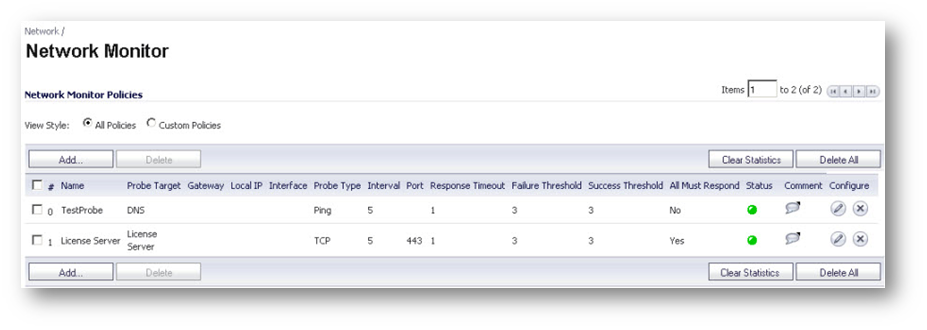
The Status column elements displays the status of the network connection to the target.
- Green indicates that the policy status is UP.
- Red indicates that the policy status is DOWN.
- Yellow indicates that the policy status is UNKNOWN.
You can view details of the probe status by hovering your mouse over the green, red, or yellow light for a policy.
The following information is displayed in the probe status
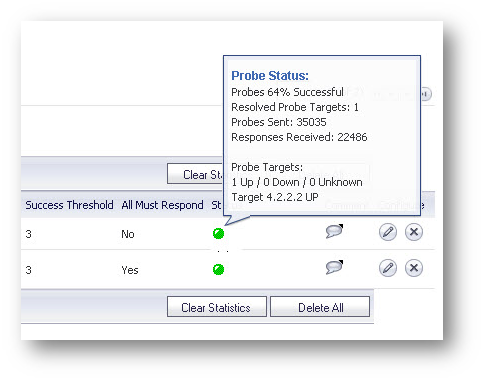
- The percent of successful probes.
- The number of resolved probe targets.
- The total number of probes sent.
- The total number of successful probe responses received.
- A list of resolved probe targets, and their status.
Adding a Network Monitor Policy
To add a network monitor policy on the SonicWall security appliance, perform these steps.
- From the Network | Network Monitor page, click Add button. The Add Network Monitor Policy window is displayed.
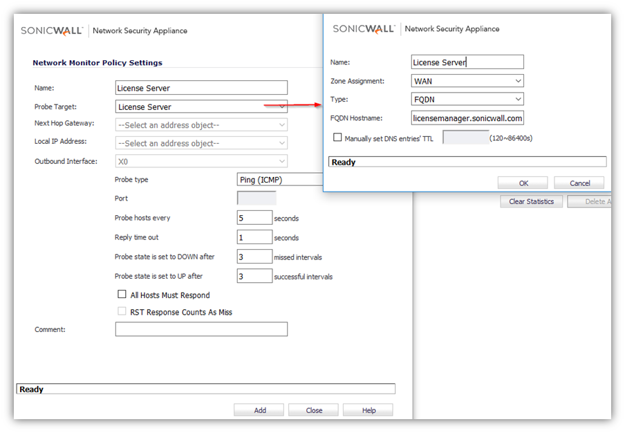
- Enter the following information to define the network monitor policy.
- Name - Enter a description of the Network Monitor policy.
- Probe Target - Select the Address Object or Address Group to be the target of the policy. Address Objects may be Hosts, Groups, Ranges, or FQDNs object. Objects within a Group object may be Host, Range, or FQDN Address Objects. You can dynamically create a new address object by selecting Create New Address Object.
- Probe Type - Select the appropriate type of probe for the network monitor policy.
- Ping (ICMP) - This probe uses the route table to find the egress interface and next-hop for the defined probe targets. A Ping echo-request is sent out the egress interface with the source IP address of the egress interface. An echo response must return on the same interface within the specified Response Timeout time limit for the ping to be counted as successful.
- TCP - This probe uses the route table to find the egress interface and next-hop for the defined probe targets. A TCP SYN packet is sent to the probe target with the source IP address of the egress interface. A successful response will be counted independently for each probe target when the target responds with either a SYN/ACK or RST via thesame interface within the Response Timeout time window. When a SYN/ACK is received, a RST is sent to close the connection. If a RST is received, no response is returned.
- Ping (ICMP) - Explicit Route - This probe bypasses the route table and uses the source IP address of the interface specified in the Outbound Interface pull down menu to send a Ping to the targets. If a Next Hop Gateway is not specified, the probe assumes that the targets are directly connected to the Outbound Interface's network.
- TCP - Explicit Route - This probe bypasses the route table and uses the source IP address of the interface specified in the Outbound Interface pull down menu to send a TCP SYN packet to the targets. If a Next Hop Gateway is not specified, the probe assumes that the targets are directly connected to the Outbound Interface's network. When a SYN/ACK is received, a RST is sent to close the connection. If a RST is received, no response is returned.
- Next Hop Gateway - Manually specifies the next hop that is used from the outbound interface to reach the probe target. This option must be configured for Explicit Route policies. For non-Explicit Route policies, the probe uses the appliance’s route table to determine the egress interface to reach the probe target. If a Next Hop Gateway is not specified, the probe assumes that the targets are directly connected to the Outbound Interface's network.
- Outbound Interface - Manually specifies which interface is used to send the probe. This option must be configured for Explicit Route policies. For non-Explicit Route policies, the probe uses the appliance’s route table to determine the egress interface to reach the probe target.
- Port - Specifies the destination port of target hosts for TCP probes. A port is not specified for Ping probes.
- Optionally, you can adjust the following thresholds for the probes.
- Probe hosts every - The number of seconds between each probe. This number cannot be less than the Reply time out field.
- Reply time out - The number of seconds the Network Monitor waits for a response for each individual probe before a missed-probe will be counted for the specific probe target. The Reply time out cannot exceed the Probe hosts every field.
- Probe state is set to DOWN after - The number of consecutive missed probes that triggers a host state transition to DOWN.
- Probe state is set to UP after - The number of consecutive successful probes that triggers a host state transition to UP.
- All Hosts Must Respond - Selecting this checkbox specifies that all of the probe target Host States must be UP before the Policy State can transition to UP. If not checked, the Policy State is set to UP when any of the Host States are UP.
- Optionally, you can enter a descriptive comment about the policy in the Comment field.
- Click Add to submit the Network Monitor policy.
 EXAMPLE: 1
Using Network Monitor Probes in Policy Based Routing
- Network Monitor policy can be used, when configuring a static route, as a condition to dynamically enable or disable the static route. When a Network Monitor policy is used, the static route is dynamically disabled or enabled, based on the state of the probe for the policy.
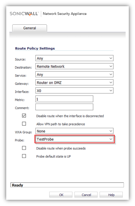
- In the example above, a static route has been created to route traffic to a remote network which is reachable through a router on the DMZ. Under the Probe a Network Monitor Policy has been selected which pings a host on the remote network. Failure of the ping will result in disabling this route.
- Typical configurations will not check the Disable route when probe succeeds checkbox, because typically administrators will want to disable a route when a probe to the route’s destination fails. This option is provided to give administrators added flexibility for defining routes and probes.
- The Probe default state is UP option is to have the route consider the probe to be successful (i.e. in the “UP” state) when the attached Network Monitor policy is in the UNKNOWN state. This is useful to control the probe-based behavior when a unit of a High Availability pair transitions from IDLE to ACTIVE, because this transition sets all Network Monitor policy states to UNKNOWN.
 EXAMPLE: 2
Using Network Monitor policies in Route Policies to dynamically Failover between VPN and MPLS connection
- This following article illustrates a scenario wherein two sites with SonicWall UTM devices are connected to each other over a direct connection or an MPLS connection. A site to site VPN connection is defined concurrently between the two sites. The primary connection between the two sites is the direct or the MPLS connection and when it fails, traffic would automatically be routed through a site to site VPN (policy based).
- For detailed instructions please refer to https://www.sonicwall.com/support/knowledge-base/configuring-vpn-Failover-using-static-routes-and-network-monitor-probes/170504720505274/.
Logs messages
- Here is a sample log message when the Network Monitoring probe goes Down.

Related Articles
- How to Block Google QUIC Protocol on SonicOSX 7.0?
- How to block certain Keywords on SonicOSX 7.0?
- How internal Interfaces can obtain Global IPv6 Addresses using DHCPv6 Prefix Delegation
Categories
- Firewalls > NSa Series > Networking
- Firewalls > NSv Series > Networking
- Firewalls > TZ Series > Networking


 YES
YES NO
NO