-
Products
-
SonicPlatform
SonicPlatform is the cybersecurity platform purpose-built for MSPs, making managing complex security environments among multiple tenants easy and streamlined.
Discover More
-
-
Solutions
-
Federal
Protect Federal Agencies and Networks with scalable, purpose-built cybersecurity solutions
Learn MoreFederalProtect Federal Agencies and Networks with scalable, purpose-built cybersecurity solutions
Learn More - Industries
- Use Cases
-
-
Partners
-
Partner Portal
Access to deal registration, MDF, sales and marketing tools, training and more
Learn MorePartner PortalAccess to deal registration, MDF, sales and marketing tools, training and more
Learn More - SonicWall Partners
- Partner Resources
-
-
Support
-
Support Portal
Find answers to your questions by searching across our knowledge base, community, technical documentation and video tutorials
Learn MoreSupport PortalFind answers to your questions by searching across our knowledge base, community, technical documentation and video tutorials
Learn More - Support
- Resources
- Capture Labs
-
- Company
- Contact Us
Configuring Isolated Links for Management and Data Uplinks on SonicWall Switch


Description
This configuration allows separate links between the firewall and switches to carry management traffic and data traffic. With a common link, the management traffic and data traffic run in the same uplink. If data traffic is congested, so is management traffic, which results in a delay in forwarding management traffic. If data traffic is congested, consider configuring separate links for management traffic and data traffic. Although similar to a common link configuration, the isolated management/data configuration runs separate uplinks for management traffic and data traffic. This configuration ensures that even with a high amount of data traffic, management traffic to the switch is forwarded without being delayed.
 NOTE: The MGMT port cannot be portshielded.
Resolution
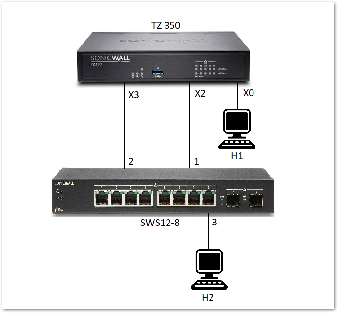
Isolated Link Topology shows an isolated link setup of a firewall with a switch:

- The link between X2 on the firewall and port 1 on the switch carries management traffic to the switch. In such a configuration, X2 is configured in the same subnet as the IP of the SonicWall Switch.
- The link between X3 on the firewall and port 2 on the switch is the uplink set up to carry PortShield traffic between H1 and H2.
- X3 is configured as the firewall uplink.
- Port 1 is configured as the switch MGMT port.
- Port 2 is configured as the switch data uplink.
- Port X2 should be configured on the same network as the switch and X3 should be left unassigned.
Isolated links for management and data traffic:
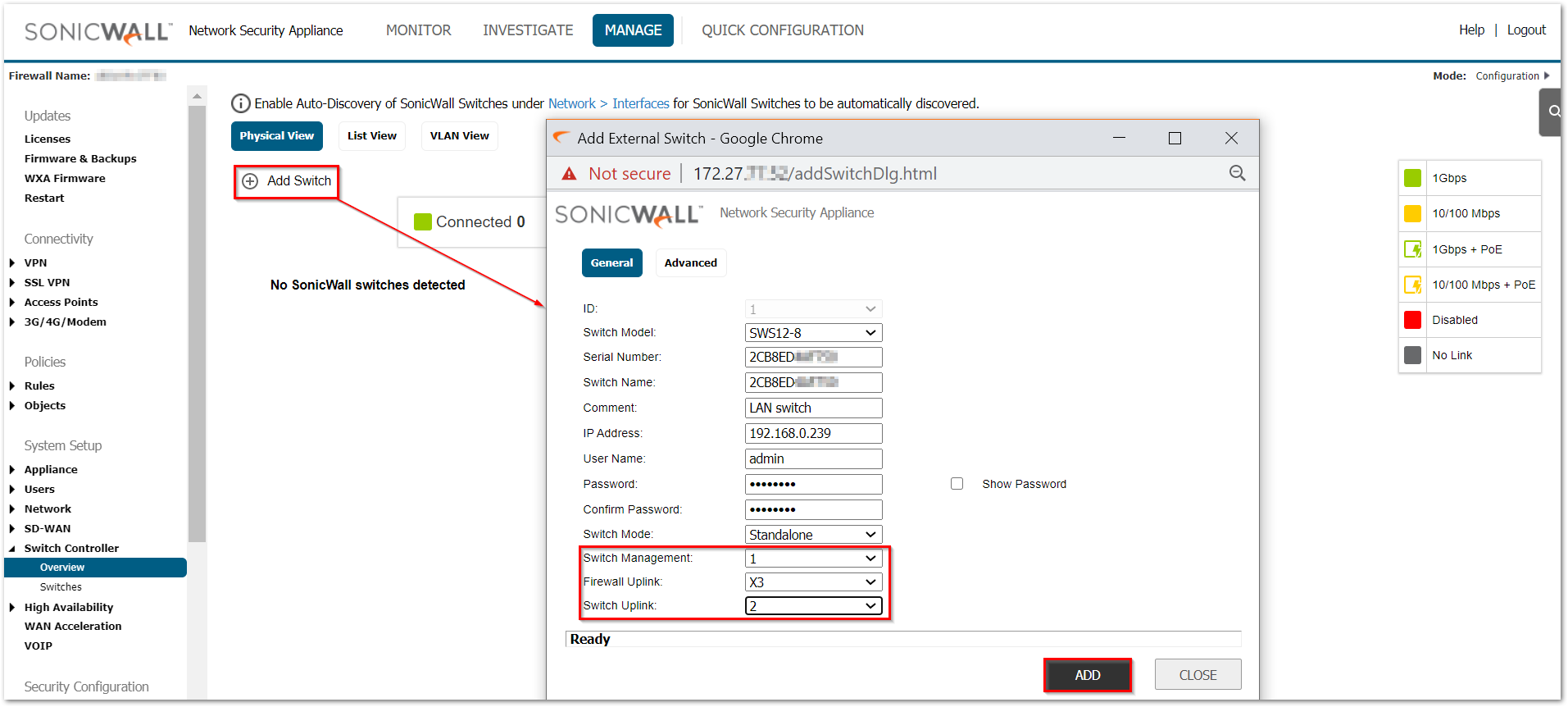
- The switch needs to be provisioned manually as when added with auto-discovery, the port that it is connected to is used for both management and data. Please refer to How To Add SonicWall Switch Manually To SonicWall UTM?
- Navigate to MANAGE | Switch Controller | Overview tab and click on Add switch button.
- Fill in all necessary information like Serial number, IP address, username, password.
- Set Switch Management to port 1, Switch Uplink to 2, and Firewall Uplink to X3.
- Click on Add

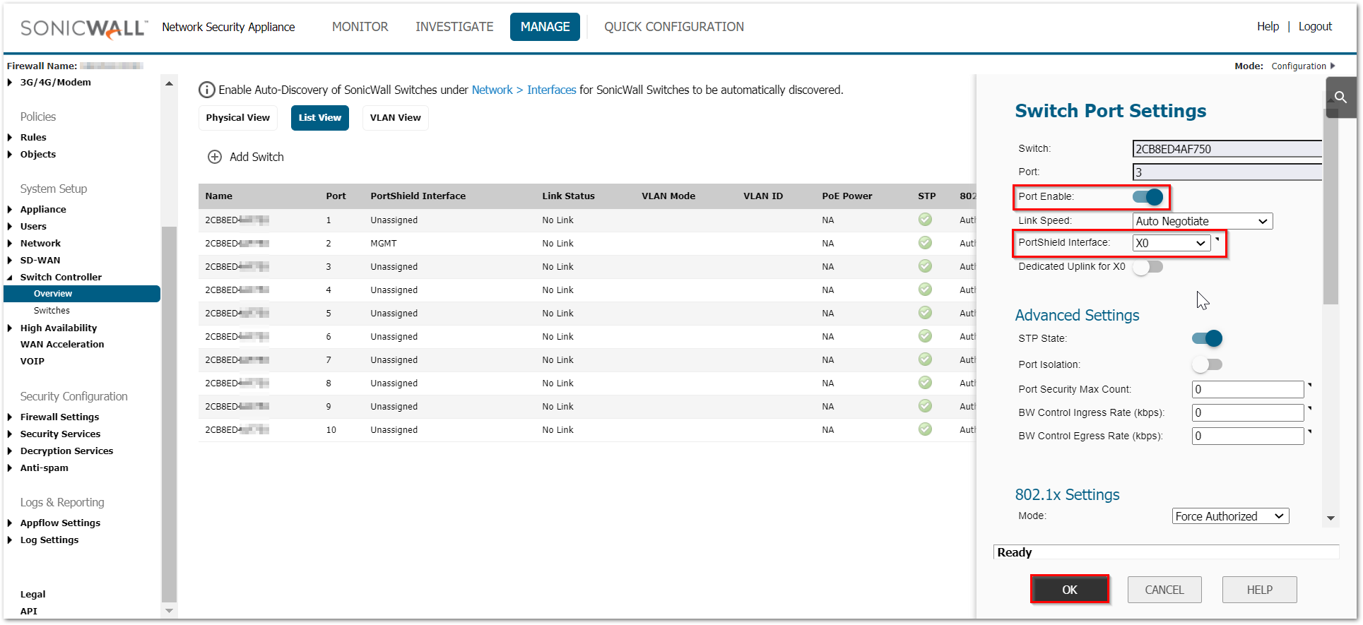
- To PortShield port 3 to X3 to support communications between H2 and H1, go to the MANAGE | Switch Controller | Overview and from either physical view, list view or VLAN view, click on Port 3.
- When the side band controls appear, look under Switch Port Settings to configure to portshield 3 to X0 as shown below. Click on OK.

 TIP: You can have VLAN sub-interfaces configured under X3 and configure other ports on the switch as part of those VLANs too. Since, X3 is unassigned, portshielding to X3 itself without any VLANs will give you the following error: 'Common uplink does not have VLAN(s) configured. Please select another Portshield interface'
Related Articles
- Supported SonicWall and 3rd party SFP and SFP+ Modules that can be used with SonicWall Switches
- How to enable Port Mirror on Sonicwall Switch.
- Create a new VLAN on Sonicwall Switch managed by WCM.


 YES
YES NO
NO