-
Products
-
SonicPlatform
SonicPlatform is the cybersecurity platform purpose-built for MSPs, making managing complex security environments among multiple tenants easy and streamlined.
Discover More
-
-
Solutions
-
Federal
Protect Federal Agencies and Networks with scalable, purpose-built cybersecurity solutions
Learn MoreFederalProtect Federal Agencies and Networks with scalable, purpose-built cybersecurity solutions
Learn More - Industries
- Use Cases
-
-
Partners
-
Partner Portal
Access to deal registration, MDF, sales and marketing tools, training and more
Learn MorePartner PortalAccess to deal registration, MDF, sales and marketing tools, training and more
Learn More - SonicWall Partners
- Partner Resources
-
-
Support
-
Support Portal
Find answers to your questions by searching across our knowledge base, community, technical documentation and video tutorials
Learn MoreSupport PortalFind answers to your questions by searching across our knowledge base, community, technical documentation and video tutorials
Learn More - Support
- Resources
- Capture Labs
-
- Company
- Contact Us
Configuring Dynamic Route Based VPN Using OSPF (Tunnel Interface VPN with Advanced Routing)


Description
This article illustrates how to configure a Dynamic Route-based VPN using OSPF. In Dynamic Route Based VPN, network topology configuration is removed from the VPN policy configuration. The VPN policy configuration creates a Tunnel Interface between two end points. Dynamic routes can then be added to the Tunnel Interface. The Dynamic Route Based VPN feature provides flexibility to efficiently manage the changes in your network.
This is an example where the Tunnel Interface is an Unnumbered Interface but borrows the IP address from a physical or virtual interface that it is bounded to.
 NOTE
NOTE
- In SonicOS GEN5 prior to 5.9 and GEN6 prior to 6.2.5.1, had no support for Numbered Tunnel Interfaces and only has support for Unnumbered Tunnel Interfaces.
- In SonicOS 5.9 and starting with 6.2.5.1 and up has support for Numbered and Unnumbered Tunnel Interfaces. With a Numbered Tunnel Interface, you can assign an IP address directly to a Tunnel Interface. For an example of configuring a Numbered Tunnel Interface VPN (Dynamic Route Based VPN), see How to Configure Numbered Tunnel Interface VPN (Route-Based VPN) in SonicOS.
- SonicOS GEN5 and GEN6 also support standard Tunnel Interface VPN or Static Route Based VPN. For an example of configuring a Static Route Based VPN, see How to configure a tunnel interface VPN (Route-Based VPN).
Dynamic route based VPN configuration is a three step process:
The first step involves creating a Tunnel Interface. The crypto suites used to secure the traffic between two end-points are defined in the Tunnel Interface.
The second step involves configuring the Routing Protocol for the Tunnel Interface.
The third step involves creating access rules from LAN/DMZ to VPN and from VPN to LAN/DMZ to allow traffic over the VPN.
The Tunnel Interface is created when a Policy of type “Tunnel Interface” is added for the remote gateway.
The Tunnel Interface must be bound to a physical interface.
The physical interface that the tunnel interface is bound to must have a physical connection (interface must be up).
 NOTE: Dynamic Route-based VPN does not work if the interface that the Tunnel Interface is bound to, is bridged to another interface.
Guidelines for Configuring Tunnel Interfaces for Advanced Routing
The following guidelines will ensure success when configuring Tunnel Interfaces for advanced routing:
- SonicWall recommends creating a VLAN interface that is dedicated solely for use as the borrowed interface. This avoids conflicts when using wired connected interfaces.
- The borrowed interface must have a static IP address assignment.
- The borrowed interface cannot have RIP or OSPF enabled on its configuration.
- The IP address of the borrowed interface should be from a private address space, and should have a unique IP address in respect to any remote Tunnel Interface endpoints.
- The Remote IP Address of the endpoint of the Tunnel Interface should be in the same network subnet as the borrowed interface.
- The same borrowed interface may be used for multiple Tunnel Interfaces, provided that the Tunnel interfaces are all connected to different remote devices.
- The physical interface must have a connection. It is possible to use the X0 or X1 interface if they are in use.
- When more than one Tunnel Interface on an appliance is connected to the same remote device, each Tunnel Interface must use a unique borrowed interface.
- Depending on the specific circumstances of your network configuration, these guidelines may not be essential to ensure that the Tunnel Interface functions properly. But these guidelines are SonicWall best practices that will avoid potential network connectivity issues.
Tasklist:
In this scenario a Dynamic Route-based VPN is configured between an NSA 2400 (Site A) and an NSA 240 (Site B). For this article, we’ll be using the following IP addresses as examples to demonstrate the VPN configuration. You can use these examples to create VPN policies for your network, substituting your IP addresses for the examples shown here:
Site A - NSA 2400
WAN (X1): 1.1.1.1
LAN (X0) Subnet: 192.168.168.0/24
DMZ (X2) Subnet: 192.168.200.0/24
LAN (X4:V30): 192.168.158.4
Site B - NSA 240
WAN (X1): 2.2.2.2
LAN (X0) Subnet: 192.168.10.0/24
LAN (X5:V16): 192.168.158.5
Resolution
Resolution for SonicOS 6.5
This release includes significant user interface changes and many new features that are different from the SonicOS 6.2 and earlier firmware. The below resolution is for customers using SonicOS 6.5 firmware.
Site A (NSA 2400) Configuration
Adding a Tunnel Interface
- Login to the SonicWall management interface.
- Navigate to Manage | VPN | Base Settings page.
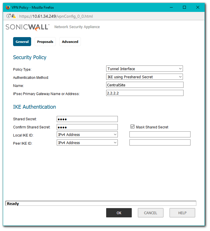
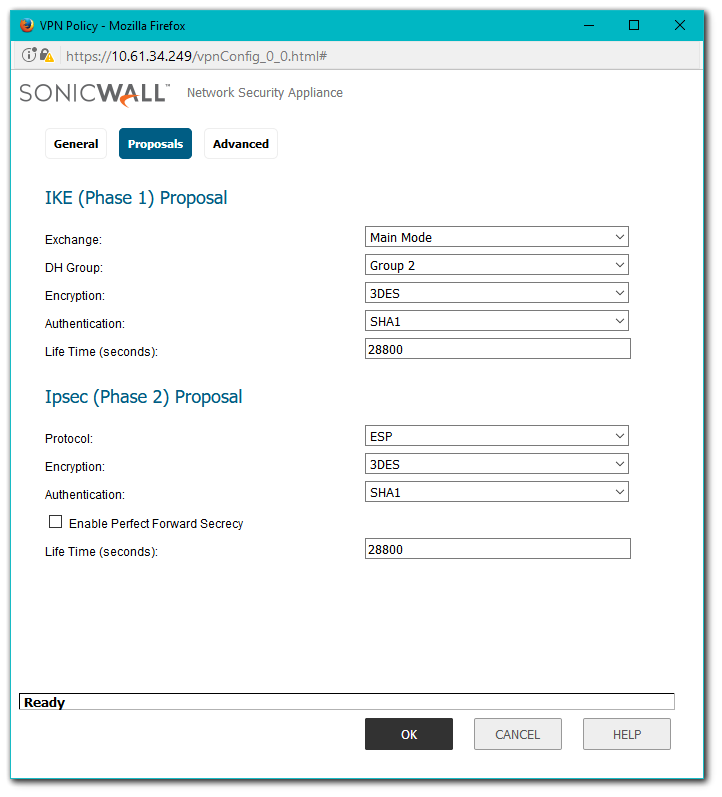
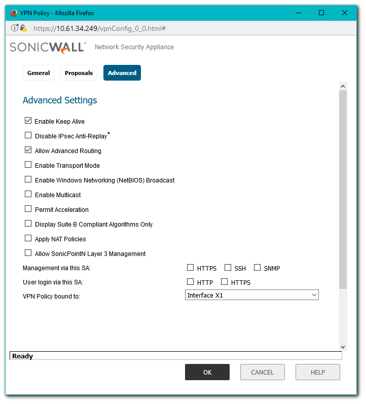
- Click on the Add button to create a Tunnel Based VPN as per the screen shots.
- Make sure you have checked the box against Allow Advanced Routing
Configuring OSPF for a Tunnel Interface
- Navigate to Manage | Network | Routing.
- Click on the Settings tab and select Advanced Routing from the Routing Mode menu.
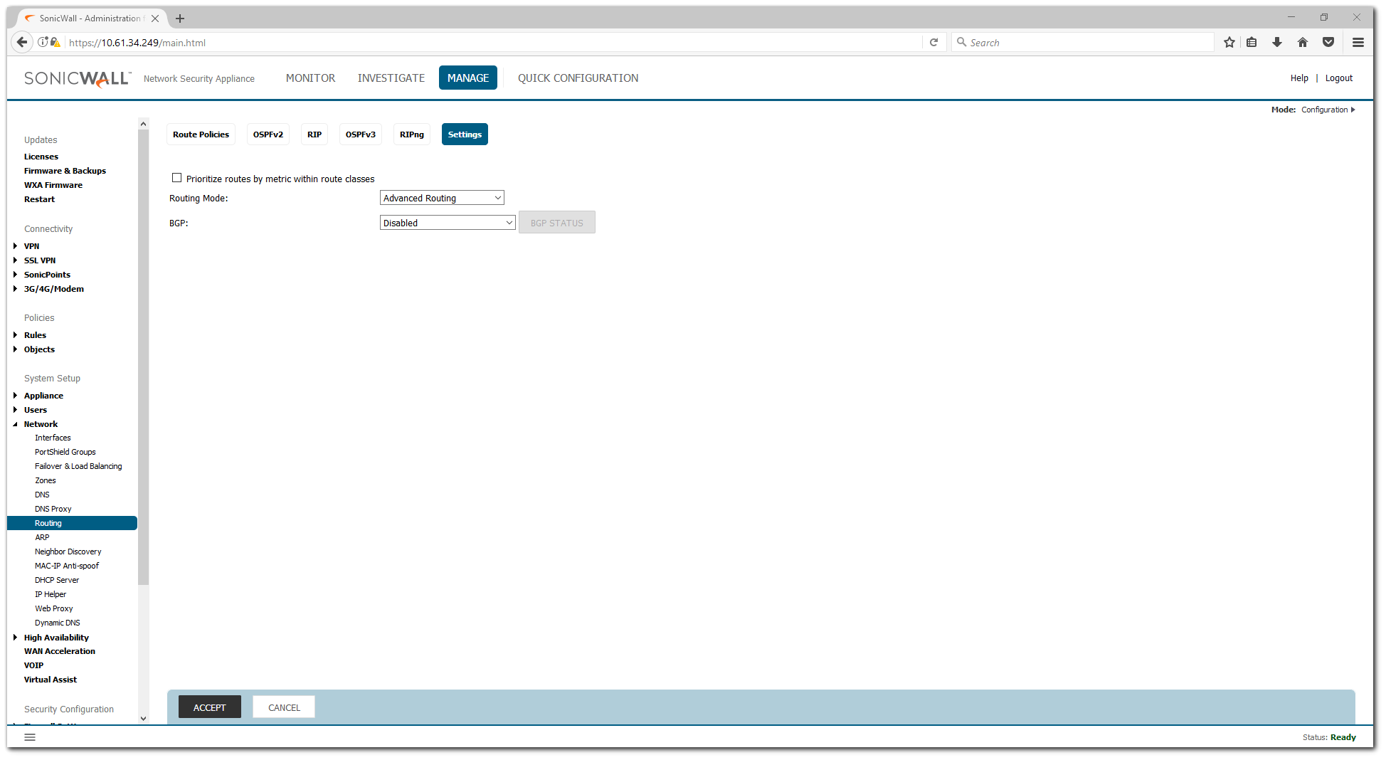
- Click on OK on the warning window.
- Click on the OSPF tab and select Configure on the Tunnel Interface (it will have the name of the VPN followed by VPN).
- Enter information in the OSPFv2 Configuration window
- OSPFv2: Enabled
- Dead Interval: 40
- Hello Interval: 10
- Authentication: Disabled
- OSPF Area: 0
- OSPFv2 Area Type: Normal
- Route Priority: 1
- The OSPF Router ID must be a unique IP address in your network.
- Click on OK to save the settings.

- IP Address Borrowed From is the interface whose IP address is used as the source IP address for the Tunnel Interface.
- This interface must have a static IP address.
- It is recommended to create a VLAN interface that is dedicated solely for use as the borrowed interface.
- The parent interface of such a VLAN interface could be either active or unassigned/unconfigured.
- The IP address of the interface selected under IP Address Borrowed From field should be in the same subnet as the Remote IP Address.
- The Remote IP Address must match the IP address of the remote site’s RIP/OSPF interface.
Adding Rules to Allow Traffic over the VPN
 CAUTION: Although the tunnel will be up and OSPF will be able to detect neighbors, traffic will be blocked to the other side of the tunnel until access rules are created from the local zones to the VPN zone.
- Navigate to Manage | Objects | Address Objects.
- Click on Add to create an address object for the destination network

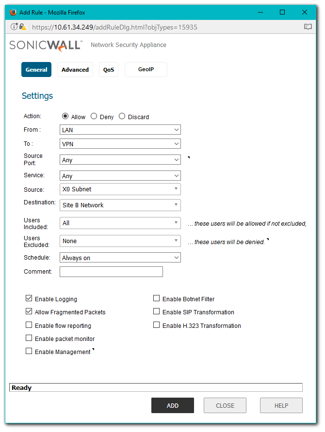
- Navigate to Manage | Rules | Access Rules.
- Change the view to From LAN To VPN at the top of the screen.
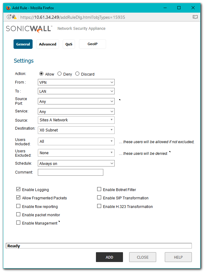
- Create an Access Rule as per the screenshot.
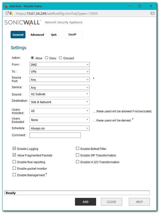
- Change the view to From DMZ To VPN at the top of the screen.
- Create an Access Rule.
- Change the view to From VPN To LAN at the top of the screen.
- Create an Access Rule.
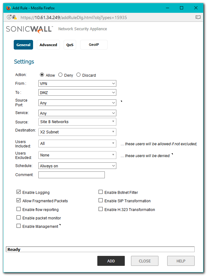
- Change the view to From VPN To DMZ at the top of the screen.
- Create an Access Rule.

Site B (NSA 240) Configuration
Adding a Tunnel Interface
- Login to the SonicWall management interface.
- Navigate to Manage | VPN | Base Settings page.
- Click on the Add button to create a Tunnel Based VPN.
- Make sure you have checked the box against Allow Advanced Routing


Configuring OSPF for a Tunnel Interface
- Follow the Steps above under "Configure OSPF for a Tunnel Interface".
Adding Rules to Allow Traffic over the VPN
 CAUTION: Although the tunnel will be up and OSPF will be able to detect neighbors, traffic will be blocked to the other side of the tunnel until access rules are created from the local zones to the VPN zone.
- Navigate to Manage | Objects | Address Objects.
- Click on Add to create an address object for the destination network.
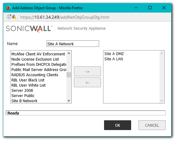
- On the same page select Address Groups from the top of the page. Add the two Address Objects to an Address Group as indicated.


- Navigate to Manage | Rules | Access Rules
- Change the view to From LAN To VPN at the top of the screen.
- Create an Access Rule.
- Change the view to From VPN To LAN at the top of the screen.
- Create an Access Rule.

Tunnel Status, OSPF Neighborship, Dynamic Routes
Once the configuration of the VPN Tunnel Interface is complete on both sites, the tunnel status will be green.

This screenshot shows the OSPF Status for the Interface and VPN. A Green Status indicates OSPF is sharing Routing information with the Neighbors while Red shows that the Neighbor is unreachable or not responding.

How to Test:
Test by pinging an IP address from one site to another. Only the subnets defined in the access rules will be accessibly.
Troubleshooting:
Check the following when the VPN tunnel is not up:
- Gateway IP address.
- Pre-shared secret
- Proposal mismatch
Check the following when the VPN tunnel is up but the VPN Tunnel Interface is unable to form neighborship:
- Make sure the interface the VPN is bound to is not configured in L2 Bridged Mode.
- Make sure the VPN Tunnel Interfaces are in the same OSPF Area
- OSPFv2 Areas Type must have the same area type on both sites. (Normal, Stub Area, Totally Stubby Area, Not-So-Stubby Area, Totally Stubby NSSA)
- OSPF Router-ID should not be duplicate.
- The interface selected under IP Address Borrowed From should be the interface to which the VPN policy is bound to.
- The Remote IP Address should match the interface IP address to which the remote VPN policy is bound to.
Check the following when the VPN Tunnel Interface has formed neighborship but dynamic routes are not present:
- Make sure the local and destination networks are not overlapping.
- Make sure Redistribute Connected Networks is checked in the OSPFv2 Configuration.
Check the following when unable to pass traffic across the tunnel even after neighborship is formed
- Make sure OSPF has dynamically learned the routes to the remote networks. Look under Route Policies via Manage | Network | Routing.
- Make sure access rules have been created from local network zones to the VPN zone.
- Make sure access rules have been created from the VPN zone to local network zones.
- The zone of local network address objects should match the zone to which that network belongs to. For eg. LAN, DMZ etc
- The destination network should be assigned zone VPN .
- Make sure no conflicting rules with higher priority are present.
- Make sure no conflicting static routes are present in the routing table. Check under Route Policies via Manage | Network | Routing.
Resolution for SonicOS 6.2 and Below
The below resolution is for customers using SonicOS 6.2 and earlier firmware. For firewalls that are generation 6 and newer we suggest to upgrade to the latest general release of SonicOS 6.5 firmware.
Site A (NSA 2400) Configuration
Adding a Tunnel Interface
- Login to the SonicWall management interface.
- Navigate to the VPN | Settings page.
- Click on the Add button to create a Tunnel Based VPN.
- Make sure you have checked the box against Allow Advanced Routing
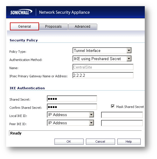
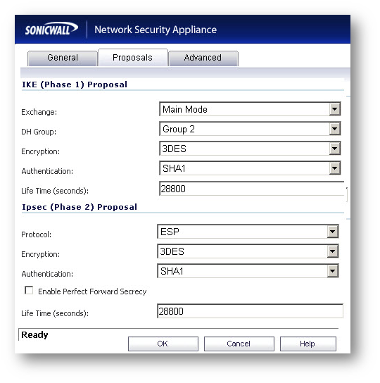
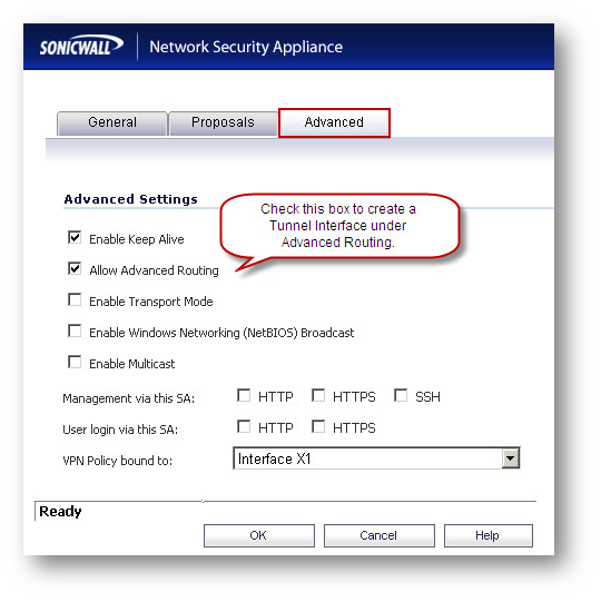
Configuring OSPF for a Tunnel Interface
- Navigate to the Network | Routing Page.
- Click on the drop-down under Routing Mode and select Advanced Routing.
- Click on OK on the warning window.
- Click on the Configure OSPF button on the Tunnel Interface (it will have the name of the VPN followed by VPN).
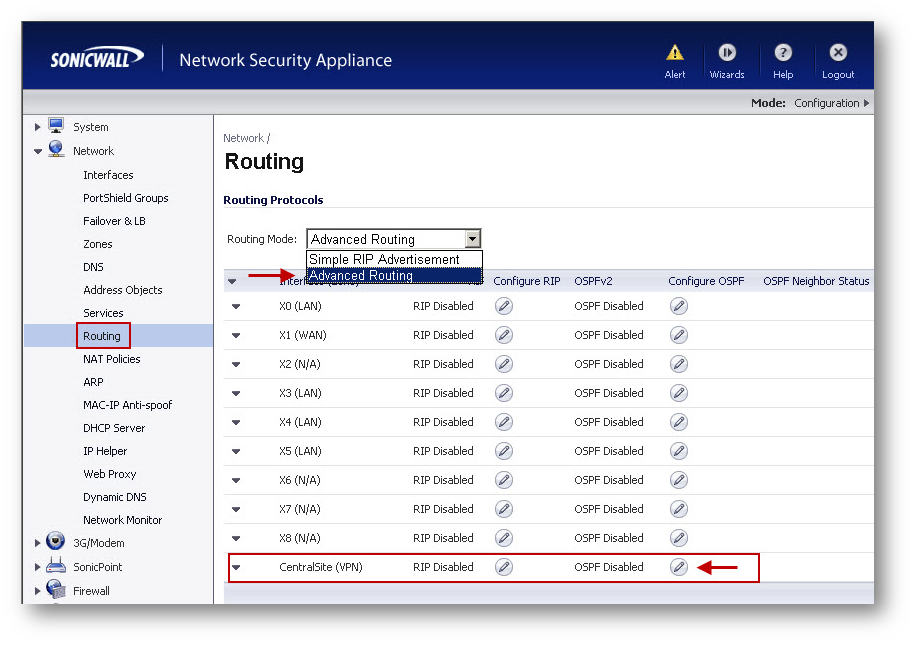
- Enter information in the OSPFv2 Configuration window.
- The OSPF Router ID must be a unique IP address in your network.
- Click on OK to save the settings.
Note:
- IP Address Borrowed From is the interface whose IP address is used as the source IP address for the Tunnel Interface.
- This interface must have a static IP address.
- It is recommended to create a VLAN interface that is dedicated solely for use as the borrowed interface.
- The parent interface of such a VLAN interface could be either active or unassigned/unconfigured.
- The IP address of the interface selected under IP Address Borrowed From field should be in the same subnet as the Remote IP Address.
- The Remote IP Address must match the IP address of the remote site’s RIP/OSPF interface.
Adding rules to allow traffic over the VPN
 NOTE: Although the tunnel will be up and OSPF will be able to detect neighbors, traffic will be blocked to the other side of the tunnel until access rules are created from the local zones to the VPN zone.
Navigate to Network | Address Objects
Click on Add to create an address object for the destination network
- Navigate to Firewall | Access Rules
- Go to LAN to VPN
- Create an access rule.
- Go to DMZ to VPN
- Create an access rule.
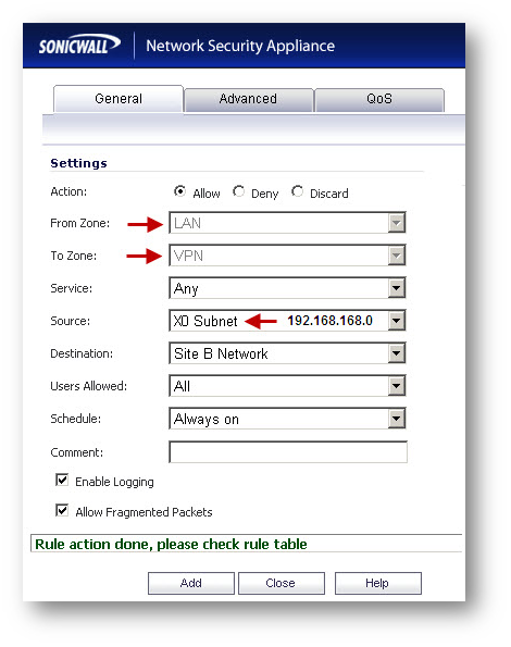
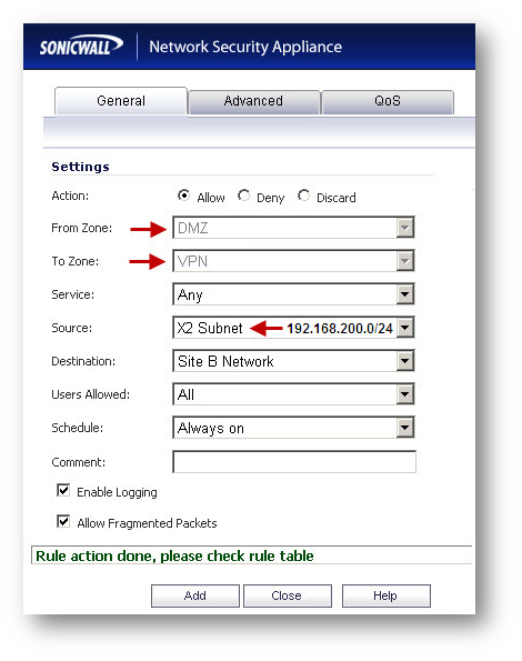
- Go to VPN to LAN
- Create an access rule.
- Go to VPN to DMZ
- Create an access rule.

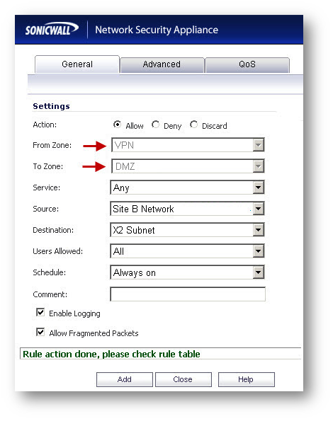
Site B (NSA 240) Configuration
Adding a Tunnel Interface
- Login to the SonicWall management interface.
- Navigate to the VPN | Settings page.
- Click on the Add button to create a tunnel based VPN.
- Make sure you have checked the box against Allow Advanced Routing


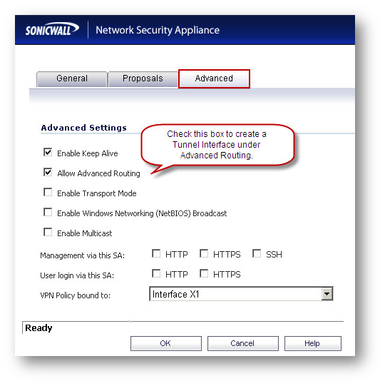
Configuring OSPF for a Tunnel Interface
- Navigate to the Network | Routing Page.
- Click on the drop-down under Routing Mode and select Advanced Routing.
- Click on OK on the warning window.
- Click on the Configure OSPF button on the Tunnel Interface (it will have the name of the VPN followed by VPN).
- Enter information as per the screenshot in the OSPFv2 Configuration window.
- The OSPF Router ID must be a unique IP address in your network.
- Click on OK to save the settings.

Note:
- IP Address Borrowed From is the interface whose IP address is used as the source IP address for the Tunnel Interface.
- This interface must have a static IP address.
- It is recommended to create a VLAN interface that is dedicated solely for use as the borrowed interface.
- The parent interface of such a VLAN interface could be either active or unassigned/unconfigured.
- The IP address of the interface selected under IP Address Borrowed From field should be in the same subnet as the Remote IP Address.
- The Remote IP Address must match the IP address of the remote site’s RIP/OSPF interface.
Adding rules to allow traffic over the VPN
Although the tunnel will be up and OSPF will be able to detect neighbors, traffic will be blocked to the other side of the tunnel until access rules are created from the local zones to the VPN zone.
- Navigate to Network | Address Objects
- Click on Add to create an address object for the destination networks and group them.


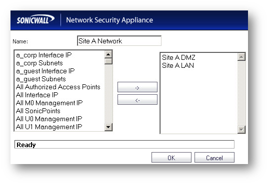
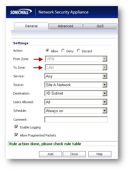
- Navigate to Firewall | Access Rules
- Go to LAN to VPN
- Create an access rule.
- Go to VPN to LAN
- Create an access rule.

Tunnel Status, OSPF Neighborship, Dynamic Routes
Once the configuration of the VPN Tunnel Interface is complete on both sites, the tunnel status will be green.
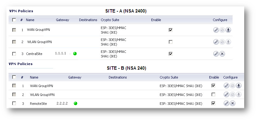
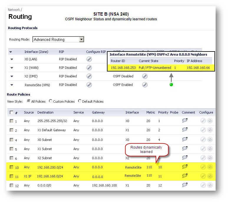
How to Test:
Test by pinging an IP address from one site to another. Only the subnets defined in the access rules will be accessibly.
Troubleshooting:
Check the following when the VPN tunnel is not up:
- Gateway IP address.
- Pre-shared secret
- Proposal mismatch
Check the following when the VPN tunnel is up but the VPN Tunnel Interface is unable to form neighborship:
- Make sure the interface the VPN is bound to is not configured in L2 Bridged Mode.
- Make sure the VPN Tunnel Interfaces are in the same OSPF Area
- OSPFv2 Areas Type must have the same area type on both sites. (Normal, Stub Area, Totally Stubby Area, Not-So-Stubby Area, Totally Stubby NSSA)
- OSPF Router-ID should not be duplicate.
- The interface selected under IP Address Borrowed From should be the interface to which the VPN policy is bound to.
- The Remote IP Address should match the interface IP address to which the remote VPN policy is bound to.
Check the following when the VPN Tunnel Interface has formed neighborship but dynamic routes are not present:
- Make sure the local and destination networks are not overlapping.
- Make sure Redistribute Connected Networks is checked in the OSPFv2 Configuration.
Check the following when unable to pass traffic across the tunnel even after neighborship is formed
- Make sure OSPF has dynamically learned the routes to the remote networks. Look under Route Policies on the Network | Routing page.
- Make sure access rules have been created from local network zones to the VPN zone.
- Make sure access rules have been created from the VPN zone to local network zones.
- The zone of local network address objects should match the zone to which that network belongs to. For eg. LAN, DMZ etc
- The destination network should be assigned zone VPN .
- Make sure no conflicting rules with higher priority are present.
- Make sure no conflicting static routes are present in the routing table. Check under Route Policies on the Network | Routing page.
Related Articles
- Error:"Invalid API Argument" when modifying the access rules
- Cysurance Partner FAQ
- Configure probe monitoring for WAN Failover and Loadbalancing - SonicWall UTM
Categories
- Firewalls > TZ Series > VPN
- Firewalls > NSa Series > VPN
- Firewalls > NSv Series > VPN


 YES
YES NO
NO