


-
Products
-
SonicPlatform
SonicPlatform is the cybersecurity platform purpose-built for MSPs, making managing complex security environments among multiple tenants easy and streamlined.
Discover More
-
-
Solutions
-
Federal
Protect Federal Agencies and Networks with scalable, purpose-built cybersecurity solutions
Learn MoreFederalProtect Federal Agencies and Networks with scalable, purpose-built cybersecurity solutions
Learn More - Industries
- Use Cases
-
-
Partners
-
Partner Portal
Access to deal registration, MDF, sales and marketing tools, training and more
Learn MorePartner PortalAccess to deal registration, MDF, sales and marketing tools, training and more
Learn More - SonicWall Partners
- Partner Resources
-
-
Support
-
Support Portal
Find answers to your questions by searching across our knowledge base, community, technical documentation and video tutorials
Learn MoreSupport PortalFind answers to your questions by searching across our knowledge base, community, technical documentation and video tutorials
Learn More - Support
- Resources
- Capture Labs
-
- Company
- Contact Us
Configuring a Tunnel Interface VPN with DHCP Relay using IP Helper
 10/14/2021
  807 People found this article helpful
 490,446 Views

Description
Configuring a Tunnel Interface VPN with DHCP Relay using IP Helper.
Resolution
Resolution for SonicOS 7.X
This release includes significant user interface changes and many new features that are different from the SonicOS 6.5 and earlier firmware. The below resolution is for customers using SonicOS 7.X firmware.
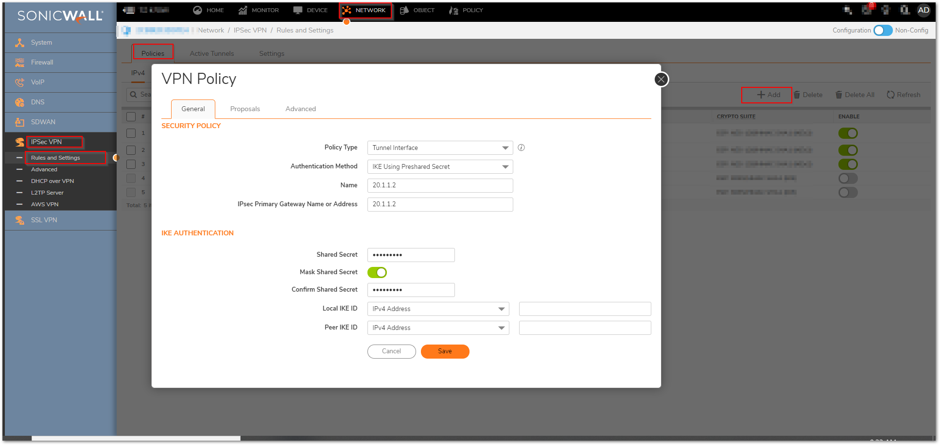
Step 1: Configure the Tunnel Interface VPN Policy on each unit. This is done under Network |IPSec VPN | Rules and Settings.
On the General tab of the new VPN Policy configuration window, configure the following settings.
- Policy Type: Tunnel Interface
- Authentication Method: IKE using Preshared Secret
- Name: Enter a desired policy name
- IPSec Primary Gateway Name/Address: Enter the remote unit’s WAN IP.
- Enter a shared secret that will be used on each side of the tunnel.
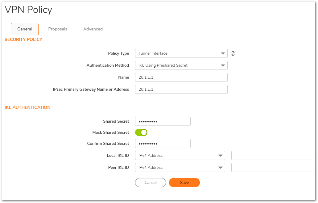
General tab (Central site):
General tab (Remote site):
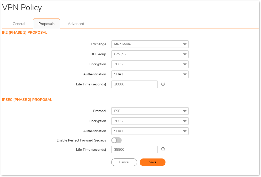
Enter your desired Proposal settings on each side of the tunnel. An example of the Proposals tab is shown below:
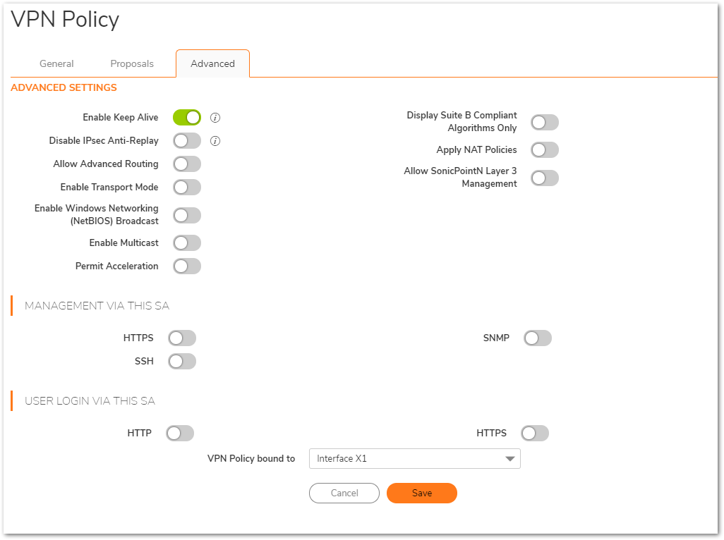
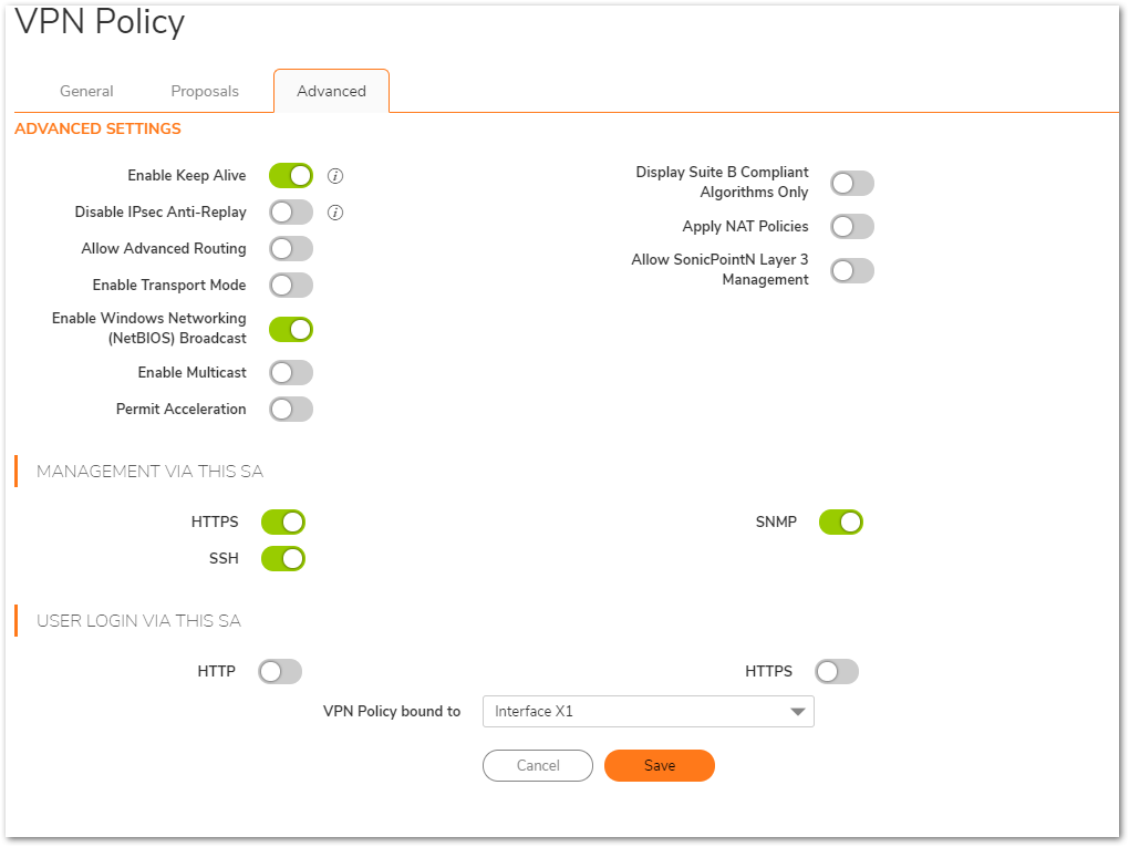
On the Advanced tab, configure Keep Alive, Management via this SA, and any other desired options. Ensure the VPN Policy bound To dropdown menu is set to the WAN Interface that the tunnel will use to connect. In this example, the X1 WAN Interface is used on the Central site, while the Remote site uses X1 WAN:
Advanced Tab(Central Site):
Advanced Tab(Remote Site):
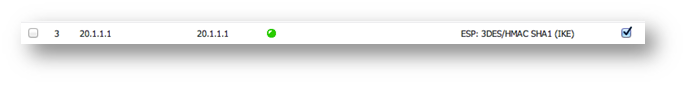
Once complete, the tunnel will be established, and will look like this:
Central Site:

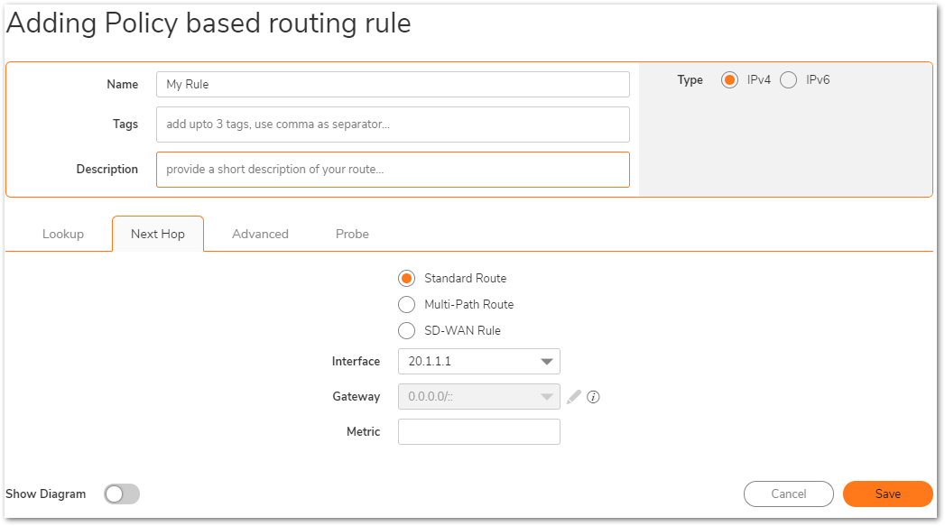
Step 2: Create routes on each unit. This can be done under Policy | Rules and Policies | Routing Rules. Options include Route-All VPN (all Internet traffic routes through the Central site over the tunnel) and the more traditional Split Tunnel VPN (only traffic destined for a remote subnet routes through the tunnel).
Address Objects can be created while creating routes, or can be done before creating routes, under Objects|Match Objects | Addresses.
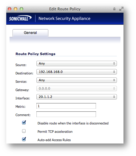
Step 2a – Central site routes:
In the example below, the Remote site has 2 networks: 1 LAN and 1 VLAN under X0. I have added one route per remote network.

Note: Create one route per remote network. The example below only shows one network route, but as shown above, two routes were created since two networks need to communicate over the tunnel.
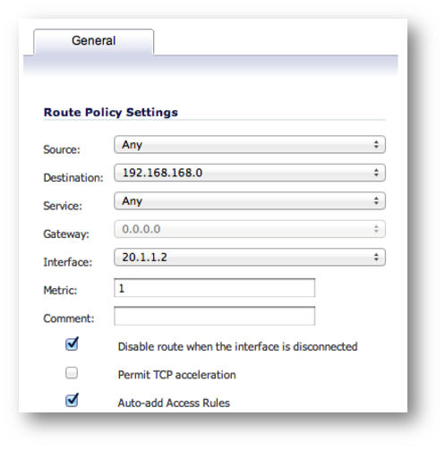
Detailed route configuration:
- Source: Any
- Destination: Remote network Address Object. The Object should be assigned to the VPN Zone.
- Service: Any
- Interface: Select the Tunnel Interface name from the dropdown list.
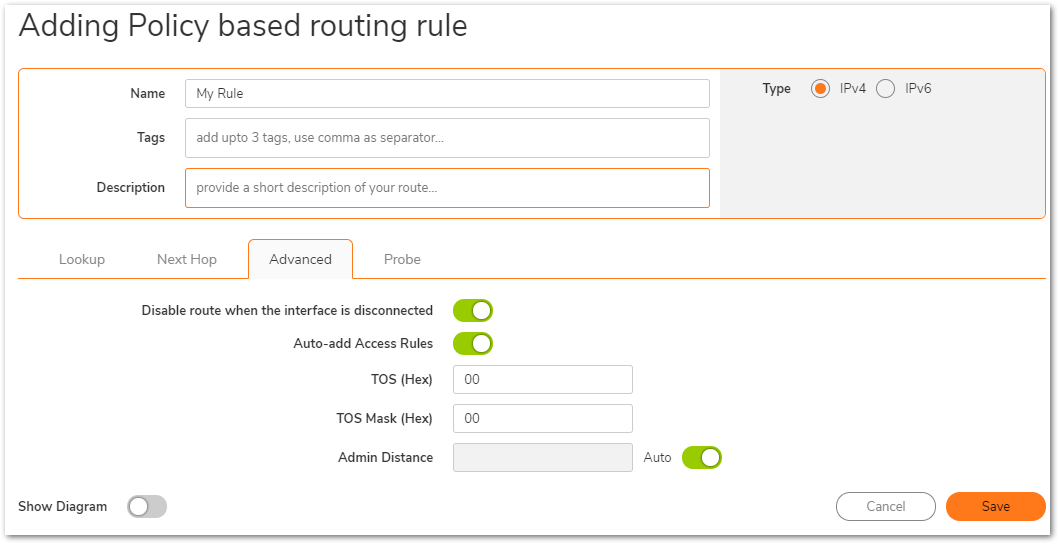
- Allow Automatic Access Rule creation for simplicity, or disable it for granularity.

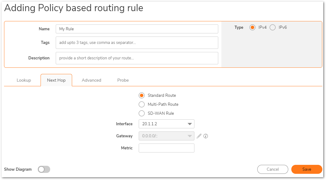
- The Same step can be configured on the remote site as well, specifying the correct tunnel interface.
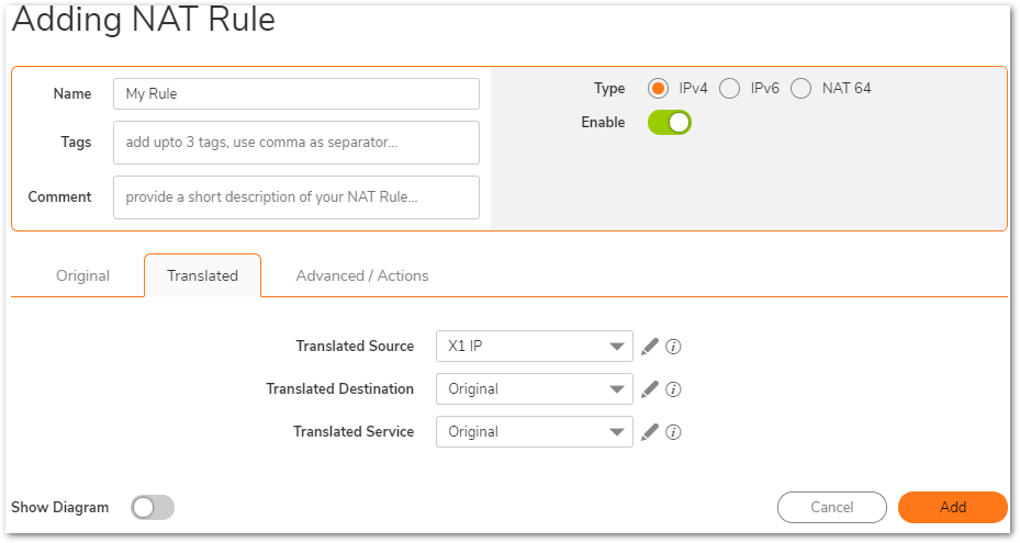
Note: If using the Route-All option, a NAT Policy must be created on the Central site for translation to the WAN IP. An example NAT Policy for the Remote site’s X0 LAN can be found below.

Split Tunnel Option: In this example, only one network exists on the Central site, thus only one route is created.

Step 3: On the Remote site, enable IP Helper and create IP Helper Policies for DHCP Relay. Options include DHCP Relay to the Central firewall’s internal DHCP server and DHCP Relay to an external DHCP server behind the Central firewall.
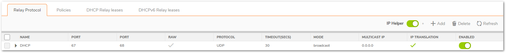
Step 3a: Enable IP Helper and DHCP Protocol Support. An example is shown below.
Under Network | System| IP Helper
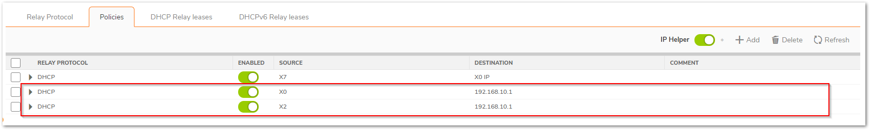
Step 3b: Configure an IP Helper Policy for each network that requires remote DHCP.
Internal DHCP Option:In this example, DHCP is relayed to the X0 LAN IP of the Central site. The Central firewall’s internal DHCP server provides DHCP to remote VPN systems.
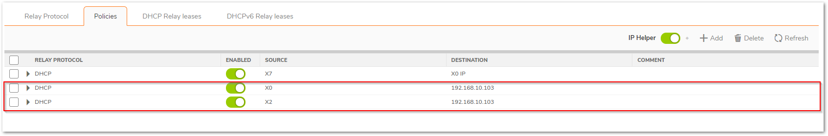
External DHCP Option: In this example, DHCP is relayed to the Central site’s LAN DHCP server. The LAN server at the Central site provides DHCP to remote VPN systems.
Step 4: Configure DHCP scopes for each remote network. Each network requires it’s own DHCP scope on the DHCP server.
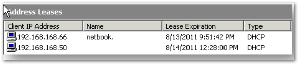
Note: DHCP Leases will be displayed on the Remote site firewall, on the Network | System| IP Helper page, as well as on the server which provided the lease.
Internal DHCP configuration:
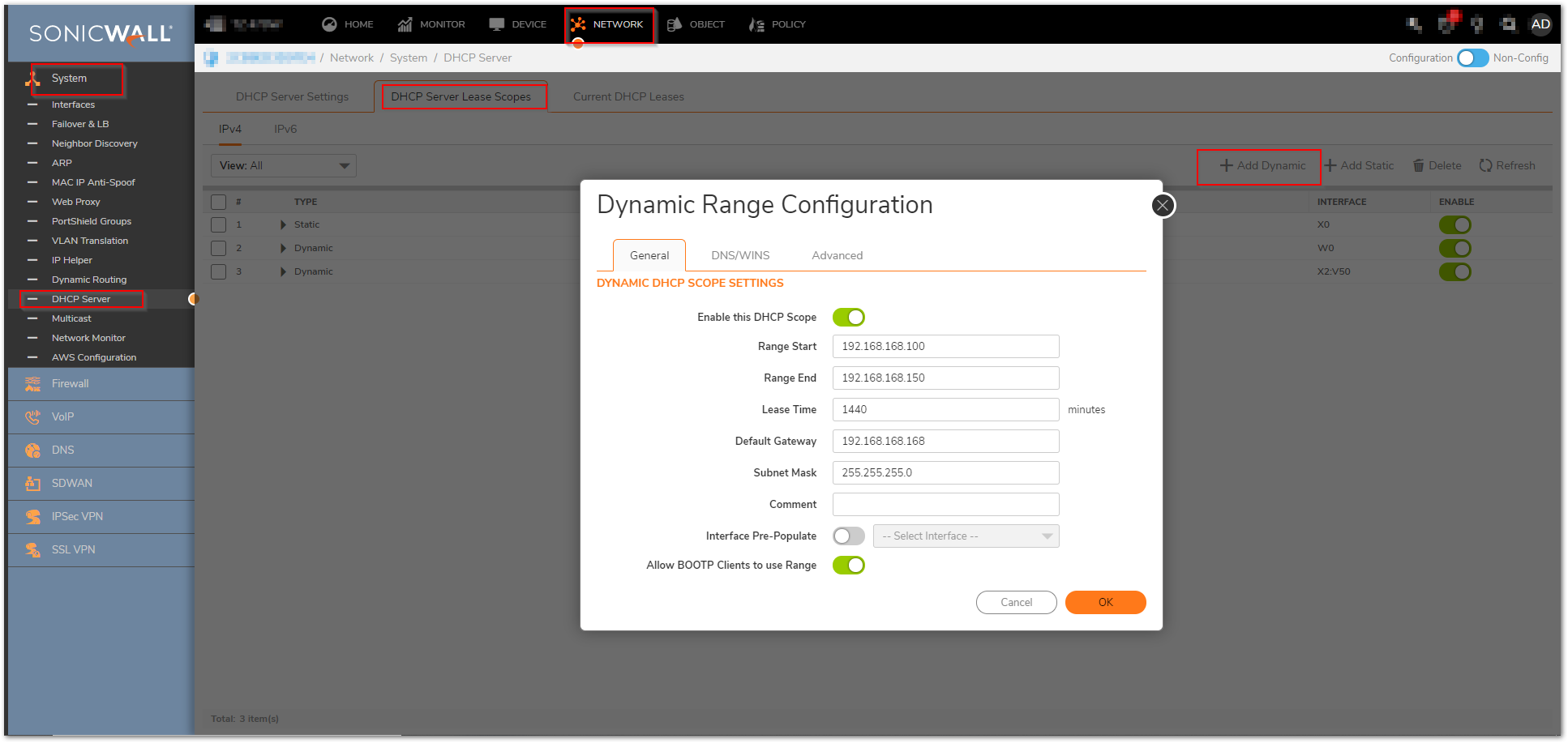
If you plan to use the Central firewall’s internal DHCP server, you will need to create a scope for each remote subnet, as shown below. This can be done on the Network >System> DHCP Server page. The scope must be large enough to support all of the DHCP clients on the remote network.
Note: Do not use the “Interface Pre-Populate” option. This will populate the DHCP scope configuration with information from the selected interface. Once the scope has been added, you will notice that the Interface reads “N/A”.
Note: Leases can be found on the Network | System | DHCP Server Lease Scopes.
External DHCP configuration:
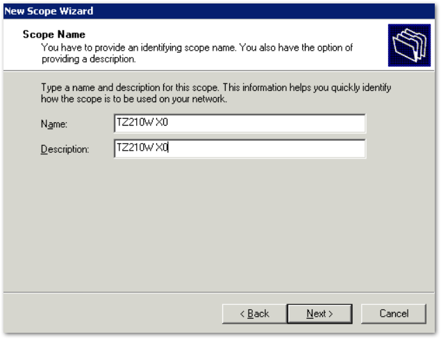
If you plan to use an external DHCP server, you will need to create a scope for each remote subnet on the DHCP server, as shown in the screenshots below. The screenshots are taken from Windows 2003 Server.
Configure the Scope’s name and description.
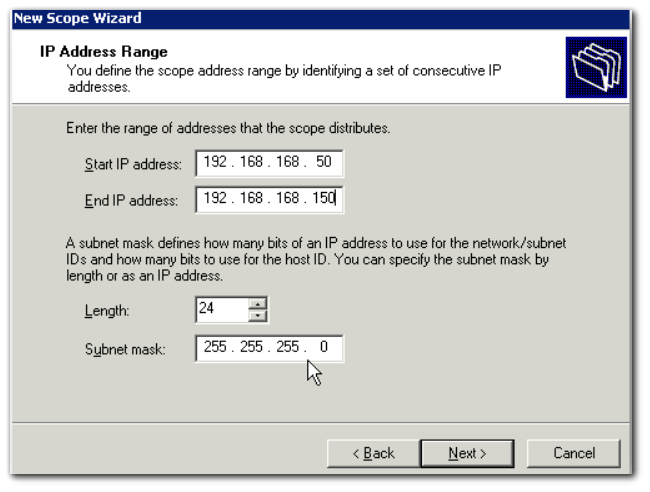
Configure the desired IP Range. Set the appropriate Subnet Mask.
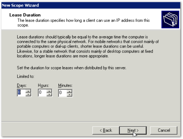
Set a DHCP Lease Duration.
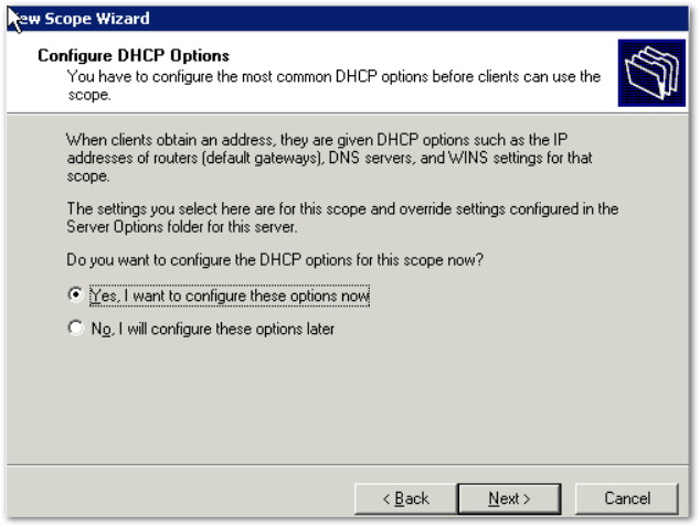
Configure the DHCP options.
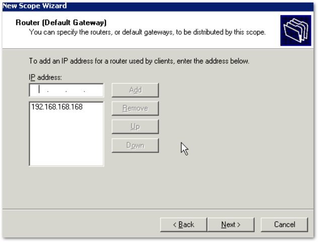
Enter the Default Gateway IP that each DHCP client will use.
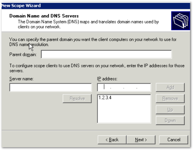
Enter the IPs of any DNS servers you would like to use.
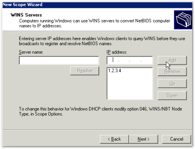
Enter the IPs of any WINS servers you would like to use.
Activate the scope.
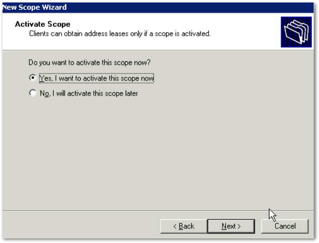
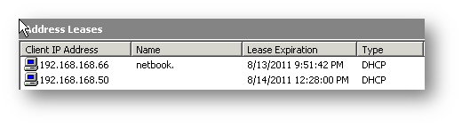
Below, the screenshots show the three configured (and active) scopes for the remote subnets, and two leases provided by the server to remote client systems.

Resolution for SonicOS 6.5
This release includes significant user interface changes and many new features that are different from the SonicOS 6.2 and earlier firmware. The below resolution is for customers using SonicOS 6.5 firmware.
Step 1: Configure the Tunnel Interface VPN Policy on each unit. This is done under Manage |VPN | Base Settings.
On the General tab of the new VPN Policy configuration window, configure the following settings.
- Policy Type: Tunnel Interface
- Authentication Method: IKE using Preshared Secret
- Name: Enter a desired policy name
- IPSec Primary Gateway Name/Address: Enter the remote unit’s WAN IP.
- Enter a shared secret that will be used on each side of the tunnel.
General tab (Central site):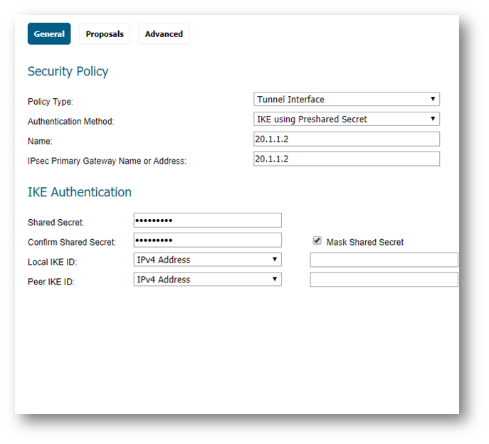
General tab (Remote site):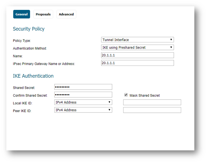
Enter your desired Proposal settings on each side of the tunnel. An example of the Proposals tab is shown below: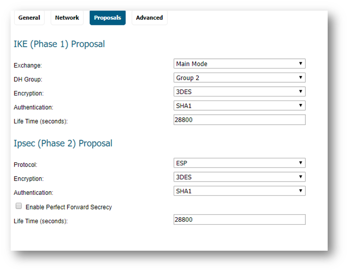
On the Advanced tab, configure Keep Alive, Management via this SA, and any other desired options. Ensure the VPN Policy Bound To dropdown menu is set to the WAN Interface that the tunnel will use to connect. In this example, the X6 WAN Interface is used on the Central site, while the Remote site uses X1 WAN.
Advanced tab (Central site):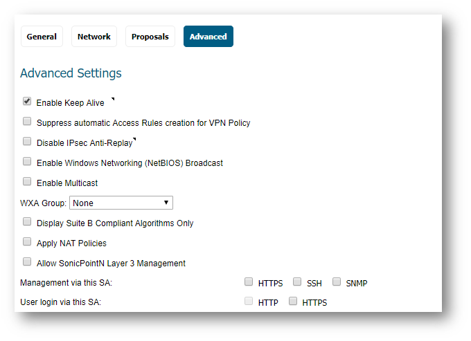
Advanced tab (Remote site):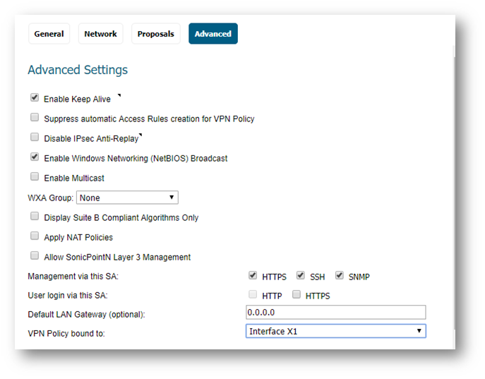
Once complete, the tunnel will be established, and will look like this:
Central: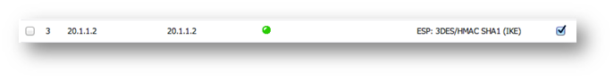
Remote:
Step 2: Create routes on each unit. This can be done under Network | Routing. Options include Route-All VPN (all Internet traffic routes through the Central site over the tunnel) and the more traditional Split Tunnel VPN (only traffic destined for a remote subnet routes through the tunnel). Address Objects can be created while creating routes, or can be done before creating routes, under Network |Address Objects.
Step 2a – Central site routes:
In the example below, the Remote site has 3 networks: 2 LANs (X0 and X2), and 1 WLAN (W0). I have added one route per remote network.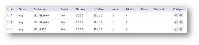
Note: Create one route per remote network. The example below only shows one network route, but as shown above, three routes were created since three networks need to communicate over the tunnel.
Detailed route configuration:
- Source: Any
- Destination: Remote network Address Object. The Object should be assigned to the VPN Zone.
- Service: Any
- Interface: Select the Tunnel Interface name from the dropdown list.
- Allow Automatic Access Rule creation for simplicity, or disable it for granularity.
Step 2b – Remote site routes:
Route-All Option: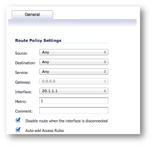
Note: If using the Route-All option, a NAT Policy must be created on the Central site for translation to the WAN IP. An example NAT Policy for the Remote site’s X0 LAN can be found below.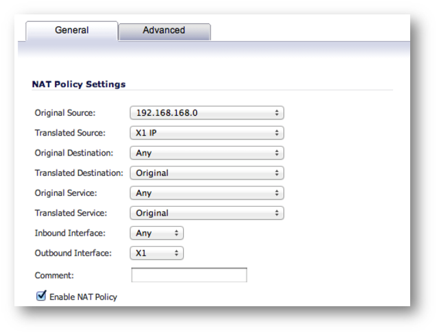
Split Tunnel Option:
In this example, only one network exists on the Central site, thus only one route is created.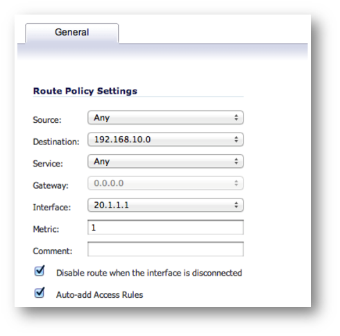
Step 3: On the Remote site, enable IP Helper and create IP Helper Policies for DHCP Relay. Options include DHCP Relay to the Central firewall’s internal DHCP server and DHCP Relay to an external DHCP server behind the Central firewall.
Step 3a: Enable IP Helper and DHCP Protocol Support. An example is shown below.
Under Manage | Network | IP Helper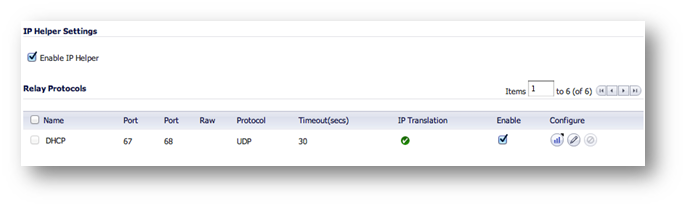
Step 3b: Configure an IP Helper Policy for each network that requires remote DHCP.
Internal DHCP Option:
In this example, DHCP is relayed to the X0 LAN IP of the Central site. The Central firewall’s internal DHCP server provides DHCP to remote VPN systems.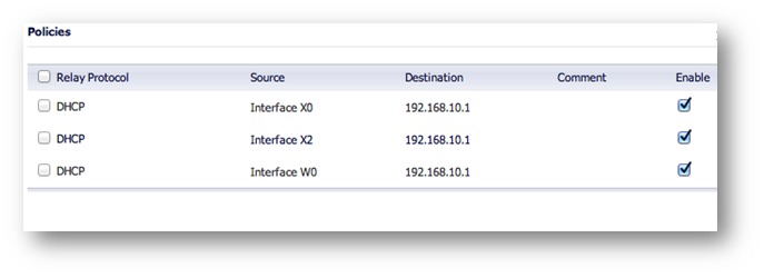
External DHCP Option:
In this example, DHCP is relayed to the Central site’s LAN DHCP server. The LAN server at the Central site provides DHCP to remote VPN systems.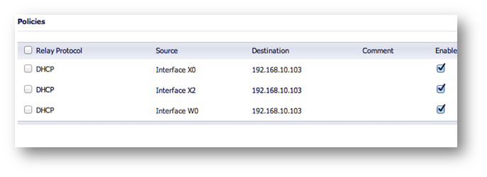
Step 4: Configure DHCP scopes for each remote network. Each network requires it’s own DHCP scope on the DHCP server.
Note: DHCP Leases will be displayed on the Remote site firewall, on the Network > IP Helper page, as well as on the server which provided the lease.
Internal DHCP configuration:
If you plan to use the Central firewall’s internal DHCP server, you will need to create a scope for each remote subnet, as shown below. This can be done on the Network > DHCP Server page. The scope must be large enough to support all of the DHCP clients on the remote network.
Note: Do not use the “Interface Pre-Populate” option. This will populate the DHCP scope configuration with information from the selected interface. Once the scope has been added, you will notice that the Interface reads “N/A”.
Note: Leases can be found on the Network | DHCP Server page.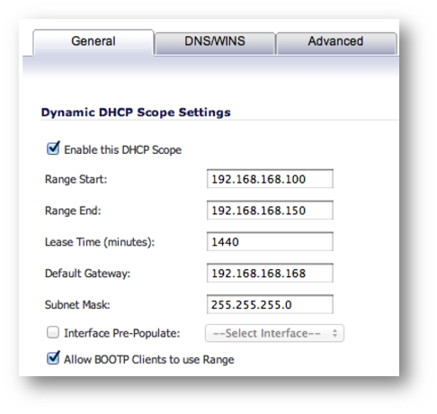
External DHCP configuration:
If you plan to use an external DHCP server, you will need to create a scope for each remote subnet on the DHCP server, as shown in the screenshots below. The screenshots are taken from Windows 2003 Server.
Configure the Scope’s name and description.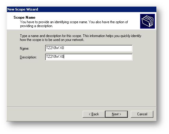
Configure the desired IP Range. Set the appropriate Subnet Mask.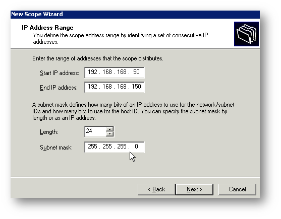
Set a DHCP Lease Duration.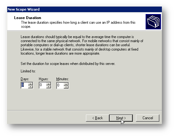
Configure the DHCP options.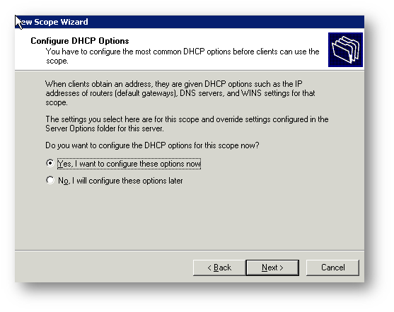
Enter the Default Gateway IP that each DHCP client will use.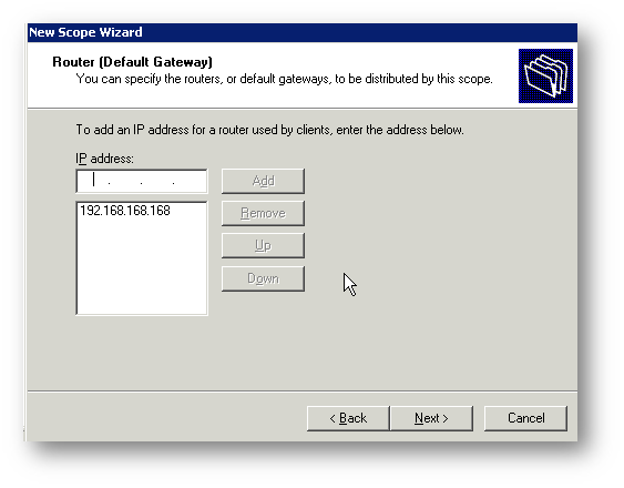
Enter the IPs of any DNS servers you would like to use.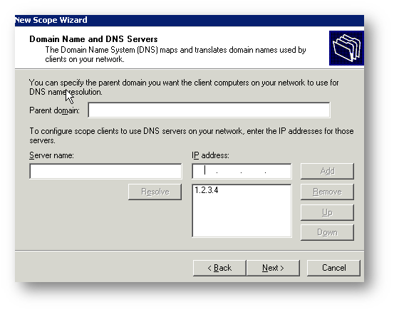
Enter the IPs of any WINS servers you would like to use.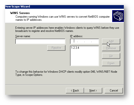
Activate the scope.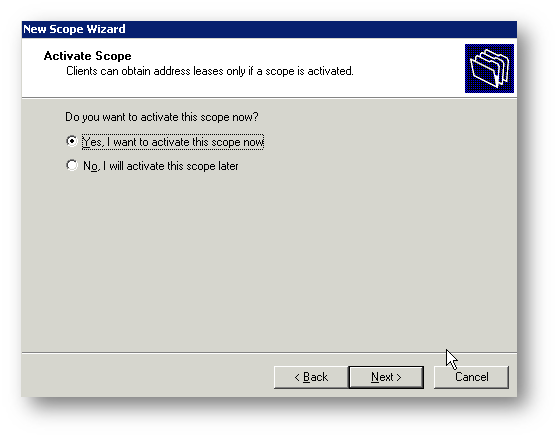
Below, the screenshots show the three configured (and active) scopes for the remote subnets, and two leases provided by the server to remote client systems.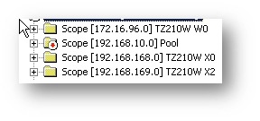
Resolution for SonicOS 6.2 and Below
The below resolution is for customers using SonicOS 6.2 and earlier firmware. For firewalls that are generation 6 and newer we suggest to upgrade to the latest general release of SonicOS 6.5 firmware.
Step 1: Configure the Tunnel Interface VPN Policy on each unit. This is done under VPN > Settings.
On the General tab of the new VPN Policy configuration window, configure the following settings.
- Policy Type: Tunnel Interface
- Authentication Method: IKE using Preshared Secret
- Name: Enter a desired policy name
- IPSec Primary Gateway Name/Address: Enter the remote unit’s WAN IP.
- Enter a shared secret that will be used on each side of the tunnel.
General tab (Central site):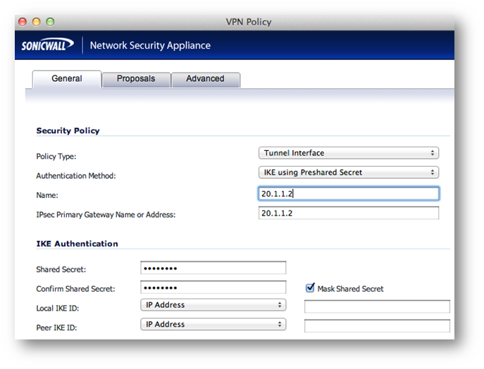
General tab (Remote site):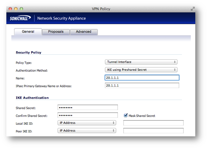
Enter your desired Proposal settings on each side of the tunnel. An example of the Proposals tab is shown below: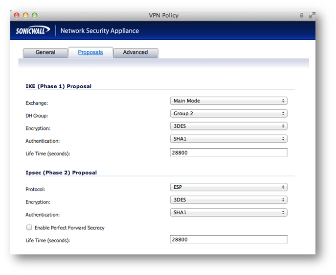
On the Advanced tab, configure Keep Alive, Management via this SA, and any other desired options. Ensure the VPN Policy Bound To dropdown menu is set to the WAN Interface that the tunnel will use to connect. In this example, the X6 WAN Interface is used on the Central site, while the Remote site uses X1 WAN.
Advanced tab (Central site):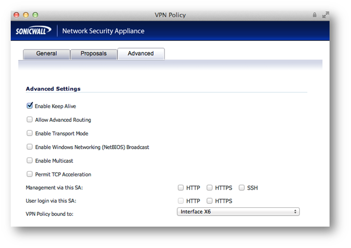
Advanced tab (Remote site):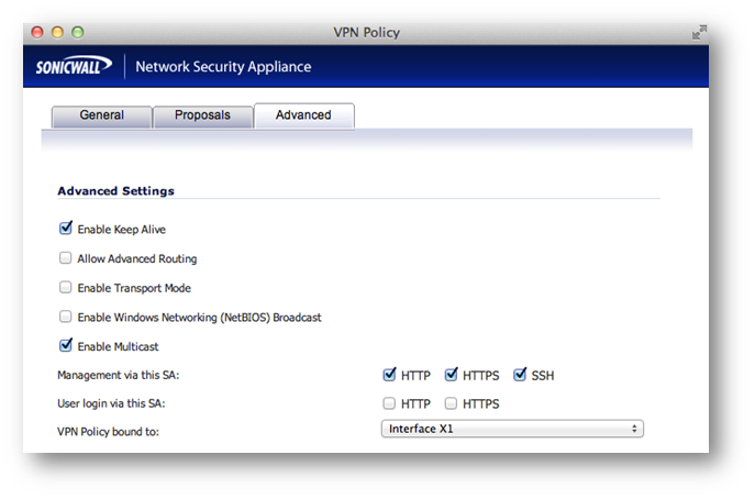
Once complete, the tunnel will be established, and will look like this:
Central:
Remote:
Step 2: Create routes on each unit. This can be done under Network > Routing. Options include Route-All VPN (all Internet traffic routes through the Central site over the tunnel) and the more traditional Split Tunnel VPN (only traffic destined for a remote subnet routes through the tunnel). Address Objects can be created while creating routes, or can be done before creating routes, under Network > Address Objects.
Step 2a – Central site routes:
In the example below, the Remote site has 3 networks: 2 LANs (X0 and X2), and 1 WLAN (W0). I have added one route per remote network.
Note: Create one route per remote network. The example below only shows one network route, but as shown above, three routes were created since three networks need to communicate over the tunnel.
Detailed route configuration:
- Source: Any
- Destination: Remote network Address Object. The Object should be assigned to the VPN Zone.
- Service: Any
- Interface: Select the Tunnel Interface name from the dropdown list.
- Allow Automatic Access Rule creation for simplicity, or disable it for granularity.
Step 2b – Remote site routes:
Route-All Option: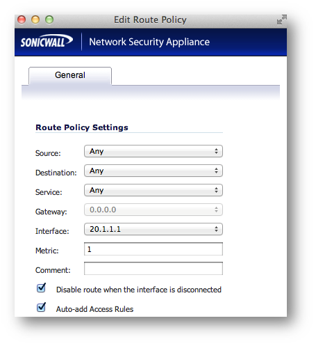
Note: If using the Route-All option, a NAT Policy must be created on the Central site for translation to the WAN IP. An example NAT Policy for the Remote site’s X0 LAN can be found below.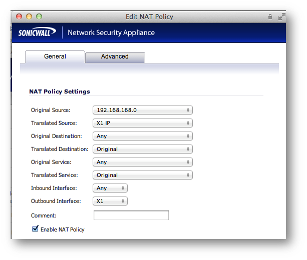
Split Tunnel Option:
In this example, only one network exists on the Central site, thus only one route is created.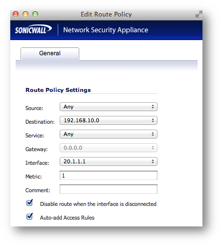
Step 3: On the Remote site, enable IP Helper and create IP Helper Policies for DHCP Relay. Options include DHCP Relay to the Central firewall’s internal DHCP server and DHCP Relay to an external DHCP server behind the Central firewall.
Step 3a: Enable IP Helper and DHCP Protocol Support. An example is shown below.
Step 3b: Configure an IP Helper Policy for each network that requires remote DHCP.
Internal DHCP Option:
In this example, DHCP is relayed to the X0 LAN IP of the Central site. The Central firewall’s internal DHCP server provides DHCP to remote VPN systems.
External DHCP Option:
In this example, DHCP is relayed to the Central site’s LAN DHCP server. The LAN server at the Central site provides DHCP to remote VPN systems.
Step 4: Configure DHCP scopes for each remote network. Each network requires it’s own DHCP scope on the DHCP server.
Note: DHCP Leases will be displayed on the Remote site firewall, on the Network > IP Helper page, as well as on the server which provided the lease.
Internal DHCP configuration:
If you plan to use the Central firewall’s internal DHCP server, you will need to create a scope for each remote subnet, as shown below. This can be done on the Network > DHCP Server page. The scope must be large enough to support all of the DHCP clients on the remote network.
Note: Do not use the “Interface Pre-Populate” option. This will populate the DHCP scope configuration with information from the selected interface. Once the scope has been added, you will notice that the Interface reads “N/A”.
Note: Leases can be found on the Network > DHCP Server page.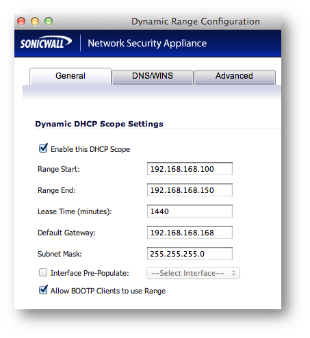
External DHCP configuration:
If you plan to use an external DHCP server, you will need to create a scope for each remote subnet on the DHCP server, as shown in the screenshots below. The screenshots are taken from Windows 2003 Server.
Configure the Scope’s name and description.
Configure the desired IP Range. Set the appropriate Subnet Mask.
Set a DHCP Lease Duration.
Configure the DHCP options.
Enter the Default Gateway IP that each DHCP client will use.
Enter the IPs of any DNS servers you would like to use.
Enter the IPs of any WINS servers you would like to use.
Activate the scope.
Below, the screenshots show the three configured (and active) scopes for the remote subnets, and two leases provided by the server to remote client systems.
Related Articles
- How to Block Google QUIC Protocol on SonicOSX 7.0?
- How to block certain Keywords on SonicOSX 7.0?
- How internal Interfaces can obtain Global IPv6 Addresses using DHCPv6 Prefix Delegation
Categories
- Firewalls > SonicWall NSA Series
- Firewalls > SonicWall SuperMassive 9000 Series
- Firewalls > SonicWall SuperMassive E10000 Series
- Firewalls > TZ Series
 YES
YES NO
NO